
Recovering Aircraft
6.1 ARRIVAL PROCEDURES
6.1.1 Entering the Carrier Control Area
Inbound flights shall normally be turned over to marshal control for further clearance to the marshal pattern. Aircraft
that were unable to check in with strike, mission, or marshal control because of communication difficulties should
proceed as directed in Figure 4-1.
Aircraft recovering aboard the CV with fuel other than JP-5 shall notify the
appropriate authority in accordance with ship/air wing SOP prior to
recovery.
6.1.2 Arrival Information
The flight leader shall provide the following information when checking in with marshal control:
1. Position
2. Altitude
3. Fuel state (low state in flight)
4. Total number of aircraft in flight (lineup)
5. Type approach requested — UTMs sweet (if applicable)
6. Other pertinent information such as navigational aid status, hung or unexpended ordnance, weather, etc., that
may affect recovery
7. COD load report.
6.1.3 Transient Helicopters
Transient helicopters approaching the carrier for landing shall contact marshal control at least 25 miles out.
During Case III, marshal control will clear helicopters to CV-3 holding or starboard delta as requested. Helicopters
unable to check in with marshal control because of communications difficulties should proceed as directed in
Figure 4-1.
6.2 CASE I
Note
Case I/II recoveries of fixed wing aircraft shall not be conducted
concurrently with Case III departures.
NAVAIR 00-80T-105
ORIGINAL 6-2
This approach may be utilized when it can be anticipated that flights will not encounter instrument conditions at any
time during the descent, break, and final approach. A ceiling of 3,000 feet and 5 miles visibility within the carrier
control zone is required. The flight leader retains full responsibility for proper navigation and separation from other
aircraft. All returning flights will check in with marshal control when entering the carrier control area or as soon as
they are released by another controlling agency. Marshal control shall acknowledge the check-in and provide the
following information:
1. Case recovery
2. Expected BRC
3. Altimeter
4. Expected “Charlie” time (if other than briefed).
Aircraft shall normally be switched to tower control at 10 nm after reporting the ship in sight (“see you”).
6.2.1 Jet/Turboprop Aircraft Port Holding/Spin Pattern
The jet and turboprop port holding pattern is a left-hand pattern tangent to the BRC or expected BRC with the ship
in the 3-o’clock position and a maximum diameter of 5 nm. Flights shall be established at their assigned port holding
pattern altitude 10 nm prior to entering the pattern. Entry shall be tangential with wings level. Minimum altitude
assignment shall be 2,000 feet MSL. A minimum of 1,000 feet vertical separation between holding altitudes shall
be maintained. The squadron/ unit recovery order and altitude assignment shall be as promulgated by ship/air wing
doctrine. All aircraft shall maintain the prescribed separation and landing order in the port holding pattern and
throughout the descent.
Departure from the port holding pattern for break entry shall be accomplished aft of the ship’s beam. Descent to the
break from the port holding pattern is commenced by the lowest aircraft or flight in time to meet the ramp time. This
descent should be planned so as to arrive at the initial (3 miles astern, 800 feet) wings level, paralleling the BRC.
Flight leaders shall exercise caution to avoid aircraft in the tanker pattern.
The flight leader shall either execute a normal break or spin for all or a portion of his flight, depending upon the
number of aircraft in the landing pattern. A spin should normally be initiated at the bow. The spin pattern shall be
flown at 1,200 feet within 3 nm of the ship. A maximum of six aircraft shall be in the landing pattern at one time.
This number may be modified by the air officer. No aircraft shall break more than 4 miles ahead of the ship. Pilots
must exercise caution to avoid departing aircraft and aircraft in the starboard holding pattern. Should a Delta be given
after commencing descent from the port holding pattern, but prior to entering the landing pattern, aircraft shall climb
or descend as required and enter the spin pattern (1,200 feet) unless specifically directed otherwise. Aircraft in the
landing pattern shall continue to maintain proper interval, flying the landing pattern at 600 feet until otherwise
directed. Flights directed to spin or reenter the port holding pattern shall climb only on the upwind or crosswind leg
ahead of the ship’s beam. Aircraft reentering the break from the spin pattern have priority over aircraft entering from
the port holding pattern.
6.2.2 COD Aircraft Starboard Holding
The starboard holding pattern shall be a right-hand racetrack pattern between 45 and 135 relative to the BRC at
500 feet or at 1,000 feet if approved by the air boss, with the closest point of approach no closer than 1 nm. When
ready, the air officer will give a Charlie to aircraft in the starboard holding pattern.
NAVAIR 00-80T-105
ORIGINAL6-3
6.2.3 Helicopters
Helicopters shall proceed to hold avoiding the areas depicted in Figure 4-3 during fixed-wing operations. Unless
previously briefed to the contrary, when more than one helicopter is operating in the holding pattern, all helicopters
shall fly a right-hand pattern at 300 feet maintaining 80 knots.
6.2.4 VFR Day Fixed Wing Carrier Landing Pattern
The landing pattern depicted in Figure 6-1 is used by fixed wing aircraft during day VFR (Case I/II) operations. The
purpose of day case I/II operations is to allow for a primarily pilot controlled pattern and reduce total recovery time
compared to case III operations.
6.2.4.1 Landing Pattern Entry
Entry into the break shall be made at 800 feet. All breaks shall be level. A descent to 600 feet to intercept the
downwind leg of the landing pattern shall commence when established downwind. Descent to 600 feet shall be
completed before reaching the 180 position.
6.2.4.2 Downwind Leg and Approach Turn
The landing pattern downwind leg is flown at 600 feet, 1 to 1-1/2 nm abeam the ship’s stern. Aircraft in the VFR Day
Landing Pattern should be established in the intended landing configuration, wings level at 600 feet with landing
checklist complete by the 180. At the 180, the aircraft should begin the approach turn and gradual descent to pass
the 90-degree position at 450 to 500 feet. The pilot should continue the approach turn until intercepting the extended
centerline of the ship’s angled deck and acquire the optical landing system meatball image. The approach turn from
the 180 to the start should take 45 seconds.
6.2.4.3 Groove and Touchdown
The aircraft should roll wings level on centerline with a centered ball to allow a 15 – 18 second groove before aircraft
touchdown on deck. At touchdown the pilot shall add power as appropriate, and prepare to bolter. Following
arrestment, the pilot shall follow the instructions of the aircraft directors and comply with the procedures in NAVAIR
00-80T-120 (CV Flight/Hangar Deck NATOPS manual).
6.2.4.4 Waveoffs
Pilots shall be prepared to be waved off at any time during a landing approach. Aircraft approaching in an unsafe
condition or situation (e.g., too low, insufficient interval, etc) will be waved off rather than be allowed to continue
to touchdown. Upon being directed to wave off, pilots shall add power as necessary to stop the aircraft’s rate of descent
and commence a climb.
6.2.4.5 Landing Pattern Upwind Leg
Once clear of the ship following a waveoff, touch and go, or bolter, the pilot shall turn to parallel the BRC. Corrections
to parallel the BRC shall not be attempted until a definite climb has been established. The climb to 600 feet landing
pattern altitude should normally be completed prior to commencing the turn to the downwind leg. Aircraft continuing
in the landing pattern shall take normal interval on other traffic in the pattern.
6.2.4.6 Landing Pattern Departure
Aircraft departing the case I/II pattern shall remain in the pattern until established on the upwind leg. From the
upwind leg, aircraft shall clear the pattern by executing a 20 turn to starboard followed by a 20 turn reversal to
parallel the BRC
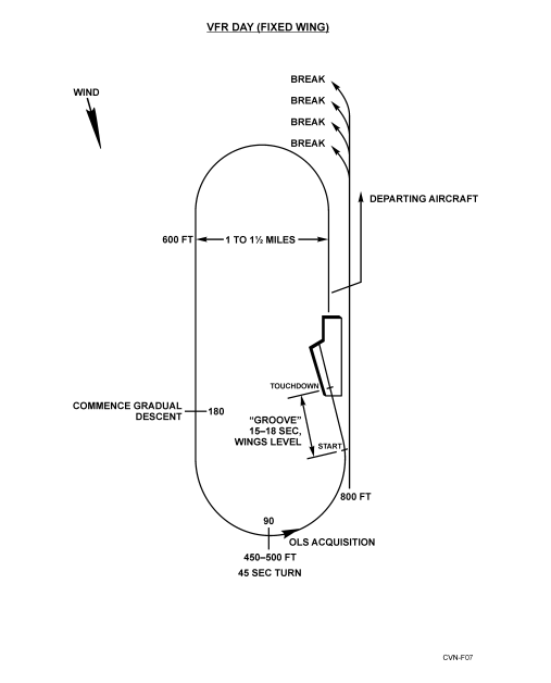 Figure 6-1. VFR Day Fixed Wing Carrier Landing Pattern
6.2.5 Voice Reports
Flight leaders shall make the following voice reports
| POSITION | REPORT |
| Descending from the port holding pattern | “Commencing” |
| Three miles astern | “Initial” |
| Entering spin pattern (when applicable) | “Spinning” |
| Departing the landing pattern to reenter port holding. | “Departing_______nm upwind” |
6.2.5.1 Low Visibility Voice Reports: Anyone Can Recommend Low Visibility Reports
The following additional calls shall be used by flight leaders upon Air Officer’s announcement of “99 low-vis-calls.”
“Commencing”
“Initial”
“Breaking at___nm”
“Departing at ___DME”
“Spin 90”
Flight leaders should amplify low-vis calls as required to add to overall situational awareness and safety of flight
(e.g. – “501, commencing from angels 4 with 2”).
6.2.6 ZIP LIP
Case I procedures shall apply, except for elimination of prescribed voice reports. The flight leader first in recovery
order shall observe the deck and plan his recovery to be at the ramp as soon as a ready deck is available. Should
unprogrammed, unbriefed, or straggler flights arrive for recovery, ZIP LIP shall be broken as required to ensure safety
of flight.
Note
ZIP LIP shall be broken anytime an apparent safety of flight situation
develops.
6.2.7 Drag
If a straight-in approach (drag) is requested, it shall be initiated at sufficient distance astern for the aircraft to be
established positively on glidepath and approach airspeed at a minimum of 1-1/2 nm for jet/turboprop aircraft.
6.3 CASE II
This approach shall be utilized when weather conditions are such that the flight may encounter instrument conditions
during the descent, but visual conditions of at least 1,000 feet ceiling and 5 miles visibility exist at the ship. Positive
control shall be utilized until the pilot is inside 10 nm and reports the ship in sight. During Case II recoveries, CATCC
shall be manned and prepared to assume control of a Case III recovery in the event weather conditions deteriorate.
The maximum number of aircraft in the landing pattern is limited to six.
Note
Case II recoveries shall not be conducted concurrently with Case III
departures. Should doubt exist regarding the ability to maintain VMC,
Case III recoveries shall be utilized.
NAVAIR 00-80T-105
ORIGINAL 6-6
Penetrations in actual instrument conditions by formation flights of more than two aircraft are not authorized. Flight
leaders shall follow Case III approach procedures outside of 10 nm. When within 10 nm with the ship in sight, flights
will be shifted to tower control and proceed as in Case I. If the flight does not have the ship in sight at 10 nm, the
flight may descend to not less than 800 feet. If a flight does not have the ship in sight at 5 miles, both aircraft shall
be vectored into the bolter/waveoff pattern and action taken to conduct a Case III recovery for the remaining flights.
Note
Weather conditions permitting, helicopters may be assigned Case I
procedures concurrently with Case II and III fixed-wing aircraft operations.
6.4 CASE III
This approach shall be utilized whenever existing weather at the ship is below Case II minimums and during all flight
operations conducted between one-half hour after sunset and one-half hour before sunrise except as modified by the
OTC or carrier commanding officer. Night/IMC Case III recoveries shall be made with single aircraft. Section
approaches will be approved only when an emergency situation exists. Formation penetrations/ approaches by
dissimilar aircraft shall not be attempted except in extreme circumstances where no safer options are available to
effect a recovery.
Note
Case III recoveries may be conducted concurrently with Case I and II
launches.
At night during VMC conditions, helicopters may be cleared to the starboard holding pattern. The same airspeed and
spacing restrictions will apply as in day VMC.
6.4.1 Marshal Procedures
6.4.1.1 Jet/Turboprop Aircraft
The primary TACAN marshal fix is the 180 radial relative to the expected final bearing at a distance of 1 mile for
every 1,000 feet of altitude plus 15 miles (angels +15). The holding pattern is a left-hand, 6-minute racetrack pattern.
The inbound leg shall pass over the holding fix. In no case will the base altitude be lower than 6,000 feet.
6.4.1.2 Helicopters
The primary TACAN marshal is the 110 radial relative to the expected final bearing at a distance of 1 mile for every
500 feet of altitude, starting at 1,000 feet and 5 miles. The holding pattern is a right-hand racetrack pattern with 2-nm
legs. The inbound leg shall pass over the holding fix.
6.4.1.3 Emergency Marshal Fixes
All fixed-wing aircraft are issued an emergency marshal radial 150 relative to the expected final bearing at a distance
of 1 mile for every 1,000 feet of altitude plus 15 miles (angels +15). Lowest altitude for assignment is 6,000 feet for
turboprop/jet. Holding sequence is jets, then turboprops. Holding procedures are right-hand, 6-minute racetrack
patterns. The inbound leg shall pass over the holding fix. Helicopter emergency marshal radial is the same as normal
helicopter marshal radial with helicopter emergency holding normally commencing at 7 miles.
6.4.1.4 Overhead Marshal
Overhead marshal may be utilized as geographical or operational circumstances necessitate. The assigned inbound
magnetic heading to the holding fix should coincide with the outbound magnetic radial of the approach. If overhead
marshal is used as the emergency marshal fix, EEATs should be every other minute.
NAVAIR 00-80T-105
ORIGINAL6-7
6.4.1.5 En Route Radar Approaches
In the event an aircraft or flight cannot reach the marshal point in time to make an assigned approach time, an en route
radar approach may be used to place the flight in the proper approach sequence.
The marshal/approach controller shall employ positive radar control and provide the pilot the purpose and a brief
description of the intended penetration whenever possible.
6.4.1.6 Marshal Altitude Assignment
Every effort should be made to anticipate weather conditions and provide marshaling in visual conditions if practical.
Aircraft below an overcast should not be required to climb into the overcast to comply with base altitude limits if
marshal control can safely exercise control below the overcast. Those aircraft above an overcast should be assigned
altitudes above the overcast and retained in formation where possible. Formation flights shall be limited to a
maximum of four aircraft at any one assigned altitude. Under instrument conditions, a section of two aircraft is the
maximum number authorized in any one flight.
6.4.1.7 Marshal Altitude Separation
Fixed-wing aircraft will normally have a minimum of 1,000 feet verical separation.Vertical separation may be
reduced to 800 feet when inside 12 nm. Helicopters shall be separated by a minimum of 500 feet vertically.
6.4.1.8 Marshal Airspeed
Aircraft will normally fly at airspeeds in accordance with the applicable aircraft NATOPS flight manual.
6.4.1.9 Bow-On-Recovery
A bow-on-recovery occurs when the marshal radial is located ahead of the carrier. Significant potential conflict exists
between departing and recovering aircraft due to airspace constraints associated with opposite direction traffic flow
and the existence of an AN/SPN-43 radar “blind spot” ahead of the ship. CATCC shall communicate
bow-on-recovery to all aircrew as soon as bow-on-recovery is determined. Departing aircraft will receive positive
control to ensure departing aircraft remain clear of recovering aircraft until course conflict is resolved. CATCC shall
provide recovering aircraft positive control and sequencing to ensure adequate separation is maintained.
6.4.2 Marshal Instructions
Marshal control shall ensure the following information has been provided each aircraft prior to entering marshal:
1. Case recovery
2. Type approach
3. Expected final bearing
4. Altimeter
5. Marshal holding instructions
6. Expected approach time
7. Expected approach button
NAVAIR 00-80T-105
ORIGINAL 6-8
8. Time check
9. Vector to marshal (if required)
10. Multiple marshal stack information (radials/altitudes).
Note
When overhead marshal is utilized, the assigned outbound penetration
bearing shall be updated during recovery to maintain a minimum of 25
clockwise from the reciprocal of the final bearing.
6.4.3 General Instructions
The following information shall be provided prior to commencing the penetration/approach:
1. Case recovery
2. Type approach
3. Final bearing
4. Weather and deck conditions
5. Divert field/fuel data
6. Time hack (30 seconds minimum) using GPS time
7. USW datum (if applicable)
8. Density altitude (if applicable)
9. MOVLAS recovery, including station number and location (tactical situation permitting)
10. COD RETRO report (if applicable).
To reduce radio traffic, items of general or collective interest may be transmitted as a “99” broadcast by marshal or
approach control.
6.4.4 Departing Marshal
Each pilot shall adjust his holding pattern to depart marshal at the assigned EAT. Early or late departure shall be
reported to marshal control immediately so that control adjustments can be accomplished if required.
6.4.5 Initial Separation
Unless weather or operating circumstances dictate otherwise, aircraft departing marshal will normally be separated
by 1 minute. Adjustments may be directed by CATCC, if required, to ensure proper separation.
6.4.6 Frequency/IFF/SIF Changes
Changes in radio communication frequencies, IFF and/or SIF mode/code that require accomplishment by the pilot
should be made no later than platform except under emergency conditions. The aircraft shall be in straight and level
flight should such changes be required below an altitude of 2,500 feet.
NAVAIR 00-80T-105
ORIGINAL6-9
6.4.7 Instrument Approach Procedures
The approaches described in this paragraph are designed primarily for single-carrier operations; however, with slight
modification, they can be used for the following:
1. Multiple-carrier operations
2. Letdown under reduced navigation and control
3. Letdown using SAR as navigational aids with AEW control
4. Recoveries during EMCON conditions.
The approach charts (Figures 6-2 to 6-5) are designed for use with all aircraft carriers regardless of weather conditions.
It is incumbent on each ship to utilize the standard approaches so that pilots may safely transition from ship to ship
or from visual to instrument conditions with a minimum change in operating procedures.
6.4.7.1 Approach Minimums
The commanding officer shall establish approach minimums that reflect significant changes in operational
capabilities, such as may be occasioned by decreased proficiency of the CATCC or embarked air wing. However,
absolute minimums are as provided in Figure 6-6 (see LSO NATOPS Manual for CARQUAL minimums).
When a suitable bingo field is available, aircraft shall not commence an approach if the reported weather is below
the minimums in Figure 6-6 unless it has been determined that the aircraft has sufficient fuel to proceed to the bingo
field in the event of a missed approach.
6.4.7.2 Penetration/Approach
1. Jet/turboprop aircraft shall descend at 250 KIAS and 4,000 feet per minute until platform is reached, at which
point the descent shall be shallowed to 2,000 feet per minute. Unless otherwise directed, aircraft shall
commence transition to a landing configuration at the 8-nm fix.
2. Helicopters shall descend at 90 knots and 500 feet per minute from marshal, crossing 145 relative to the final
bearing at or above 900 feet. Unless otherwise directed, helicopters shall commence transition to a landing
configuration prior to the 3-nm fix.
6.4.7.3 Correcting to the Final Bearing
1. Jet or turboprop aircraft on the CV-1 approach will correct from the marshal radial to the final bearing at 20
miles in the following manner:
a. The pilot shall make a gradual correction when the final bearing is within 10 of the reciprocal of the
marshal radial.
b. The pilot shall turn 30 when the final bearing is greater than 10 from the reciprocal of the marshal radial.
If not established on the final bearing at 12 miles, the pilot shall fly the 12-mile arc until intercepting final
bearing.
2. Aircraft on the CV-2 approach shall correct to the final bearing in the following manner:
a. If final bearing decreases, fly 90 of penetration turn and arc to the new final bearing.
b. If final bearing increases, fly the standard penetration turn continuing to intercept the new final bearing prior
to the 10-mile DME fix.
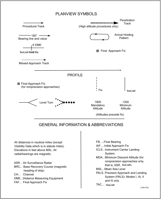 Figure 6-2. Legend Chart for Aircraft Carrier Instrument Approach Proceduress
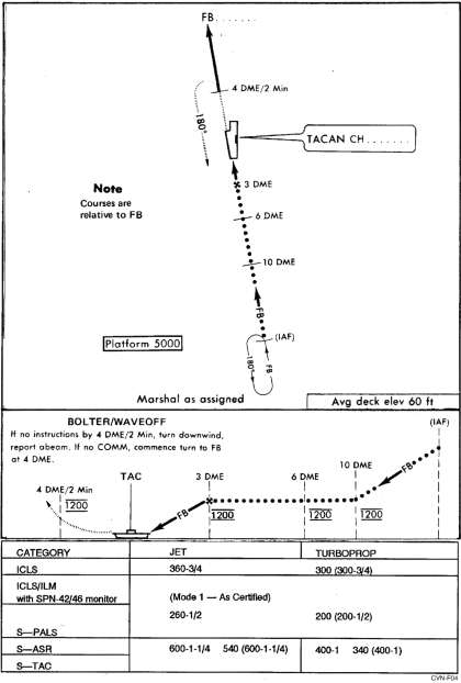
Figure 6-3. Approach Chart CV-1 TACAN (Jet and Turboprop)