Sources
- CV-NATOPS
- Preparing for Flight Operations
- Air Traffic Control Doctorine
- Launching Aircraft
- Recovering Aircraft
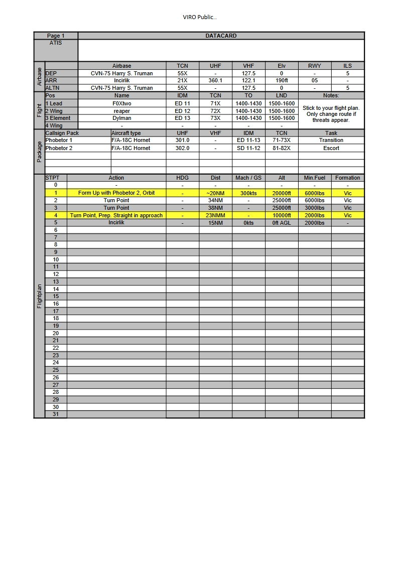
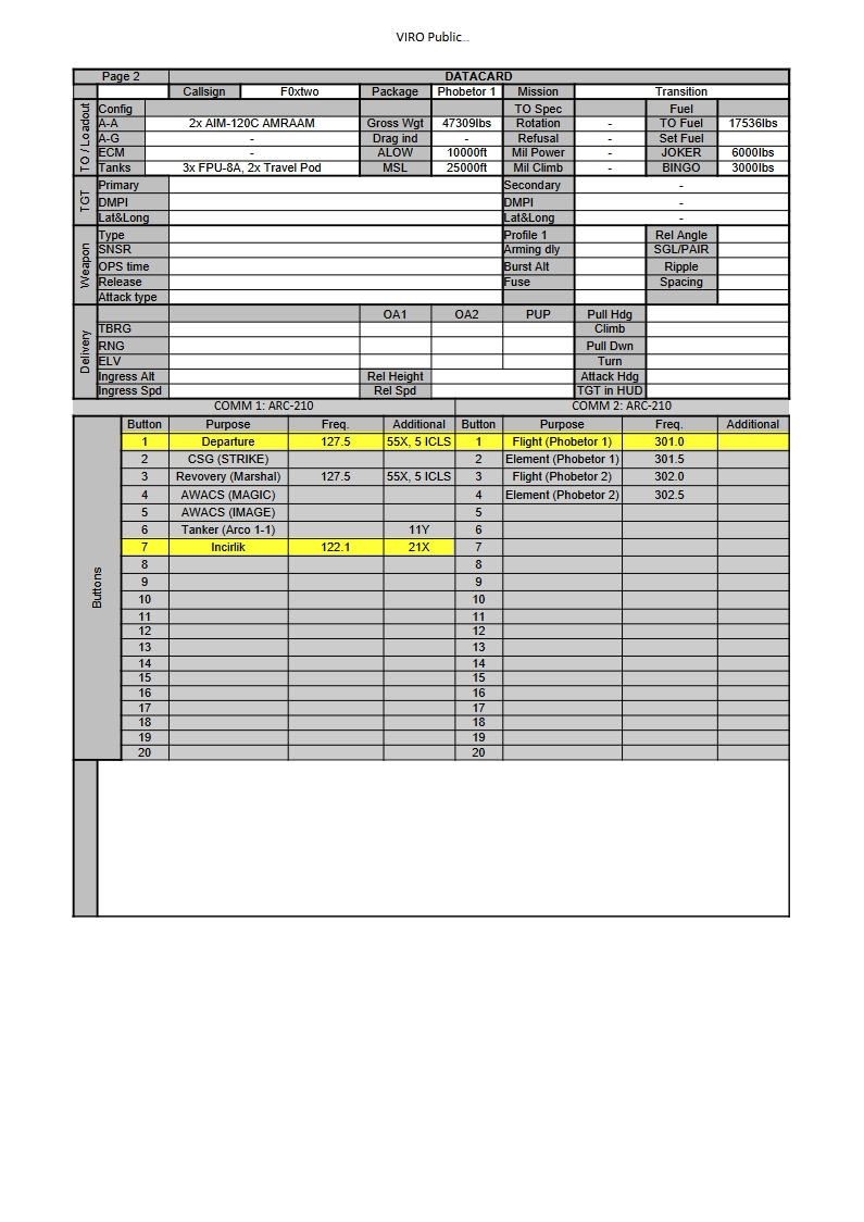
- Flight Documents
CV-NATOPS
Summary of CV-NATOPS pdf
Full document can be found discord or clicking here
Preparing for Flight Operations
3.1 THE AIR PLAN
To obtain maximum efficiency from personnel and equipment, carrier air operations must be precisely scheduled in
every respect. Air operations and strike operations are the coordinating and scheduling agencies for all flight
operations. The strike operations officer will collect all required flight information for preparation of the daily air
plan that will be submitted to the operations officer via the air operations officer, for approval and signature.
In order for strike operations to prepare an air plan that is within the capabilities of the air wing and all supporting
activities, the following must be reported on a regular basis:
- An up-to-date inventory of aviation ordnance on board and available for the next day’s operation.
- The status of all embarked aircraft. This report shall be delivered to the bridge, flag bridge, flag operations,
air operations, and the air department. In addition to current aircraft status, the report should include expected
changes in status and test flight requirements for the following day. - Air intelligence information concerning the next day’s operation.
Normally, the air plan will be distributed on the evening before the scheduled operations. When the air plan is delayed,
the strike operations watch officer shall provide advance information to allow preparations for the first flights. As
a minimum, air ops, flight deck control, PriFly, the air department duty officer, all ready rooms, CVIC, the ship’s
ordnance handling officer, and CDC shall be advised of the following:
- Launch times
- Mission
- Flight composition
- Fuel requirements
- Ordnance loading.
The air plan shall include the following:
- Event number
- Launch time
- Recovery time
- Mission
- Number and model of aircraft, including spares
- Squadron and radio call
- Total sorties
- Sunrise, sunset, moonrise, moonset, phase
- Date
- Fuel
- Alert aircraft
- Logistics aircraft
- Tactical frequencies
- Notes as required. Notes shall include the following:
- EMCON/ZIP LIP conditions
- Ready deck schedule
- Any other information required including restrictions or hazards to flight.
Upon receipt of the daily air plan, each squadron shall prepare and distribute its flight schedule as required. This
schedule shall designate pilots, radio calls, and the mission for each flight assigned. It is the responsibility of the
aircraft handling officer to ensure strict conformance to the air plan.
3.1.1 The Ordnance Load Plan
Strike operations shall prepare an ordnance load plan that will be utilized as a supplement to the air plan for aircraft
ordnance loads. No changes will be made to the ordnance load plan without approval by the strike operations officer.
It is the responsibility of the aircraft handling officer to ensure strict conformance to the ordnance load plan.
3.3 BRIEFING
It is the responsibility of squadron or unit commanders to ensure all flightcrews have been properly briefed and have
sufficient information to complete the assigned mission. Briefing checkoff lists shall be used as required by
applicable aircraft NATOPS flight manuals. Each briefing must include EMCON procedures, if applicable, and
procedures to be followed in the event of communication or NAVAID failure.
Air ops shall provide the following prelaunch briefing information 2-1/2 hours prior to each event:
- Launch and recovery times
- Launch and recovery PIM
- NAVAID status and frequencies
- Ship’s weather
- Weather at bingo fields and en route
- Emergency data
- Bearing and distance to nearest land
- Bearing and distance to nearest suitable landing field
- NAVAIDs, frequencies, and facilities at nearest field
- Ready carrier-call, frequencies, NAVAIDs, and PIM
- Expected final bearing
- Emergency marshal fixes/altitudes/approach times.
- Air traffic control data
- Departure/rendezvous radials
- Departure frequency and IFF/SIF mode and code
- Special procedures for ZIP LIP/EMCON conditions (if in effect).
- Any restrictions or hazards to flight
- Pertinent information not included in the air plan.
CATCC shall provide to all aircraft not embarked in the ship, but engaged in any support operations (COD, VOD,
etc.) that require them to recover aboard and launch again, all applicable items in the CATCC provided briefing
information listed above.
3.4 FLIGHT PLANS AND ADVISORIES
The requirements for filing flight plans and advisories vary with each operating area and are contained in the DoD
Flight Information Publications (FLIPs) and fleet operating directives. As a rule, flight plans will be required for
flights that:
- Terminate ashore
- Proceed across ADIZ boundaries and are not covered by a flight advisory
- Proceed over land.
Flight advisories shall be filed for flights within ADIZ boundaries by all aircraft that will land back on board ship
and are not covered by a flight plan. Squadrons shall file flight plans (DD175/DD1801) with CATCC to meet time
requirements established by applicable operating area manuals or ICAO guidelines.
3.4.1 Close Proximity Operations
During concurrent flight operations by two or more CVs/LHAs/LHDs, or concurrent operations between a
CV/LHA/LHD and other aviation-capable ships (fixed wing or helicopter), each ship should remain in its assigned
disposition in order to reduce air traffic coordination problems. CATCC/AOCC or HDC must closely monitor and
coordinate flight patterns to avoid mutual interference. Prelaunch procedures shall include exchange of air plans and
prelaunch notification by aviation-capable ships and acknowledgment by the CV/LHA/LHD prior to any flight
operations within 10 nm of the CV/LHA/LHD.
Air Traffic Control Doctorine
4.1 RESPONSIBILITIES
4.1.1 Operations Officer
4.1.2 Air Operations Officer
The air operations officer is responsible to the operations officer for coordination of all matters pertaining to flight
operations, the proper functioning of the CATCC and shall determine the type of approach and required degree of
control.
4.1.3 Air Officer
The air officer determines the case launch and/or recovery. The air officer is also responsible for visual control of all
aircraft operating in the carrier control zone. Under Case I and II conditions, this responsibility may be extended
beyond the carrier control zone to include all aircraft that have been switched to air officer’s control frequency. For
special operations such as bombing a sled or air demonstrations, the air officer may exercise control outside of the
carrier control zone. Additionally, the air officer is the carrier control zone clearing authority. Agents desiring to
operate aircraft within the control zone must obtain the air officer’s approval prior to entry. This clearance shall
include the following:
- Operating instructions as required for avoiding other traffic
- Information concerning hazardous conditions
- Altitude and distance limitations to which aircraft may be operated.
4.1.4 Landing Signal Officer
The LSO, under supervision of the air officer, is responsible for the visual control of aircraft in the terminal phase
of the approach immediately prior to landing. LSO specific responsibilities are delineated in the LSO NATOPS
Manual (NAVAIR 00-80T-104).
4.1.5 Landing Signalman Enlisted
The LSE, under the supervision of the air officer, is to ensure helicopters, on signal, are safely started, engaged,
launched, recovered, and shut down. The LSE receives his directions from PriFly via light signals and/or two-way
flight deck communications. It is his responsibility to ensure all tiedowns are removed prior to lift-off and that the
aircraft is properly secured after landing. All signals given by the LSE are advisory with the exception of the
“waveoff” and “hold,” which in all cases are mandatory. During vertical replenishment operations, the LSE directs
the helicopter over the deck and provides signals for the delivery and hookup of cargo. Ensure LSE and Army aircrews
are familiar with engagement/disengagement procedures of rotors, prior to recovery/launch operations.
4.1.6 Pilots
4.1.7 Combat Direction Center Officer
The CDC officer is responsible for mission control of aircraft assigned to him. This includes providing separation
from other aircraft operations in the vicinity of the carrier and ensuring intercept/mission controllers know the basic
procedures for air traffic control. Additionally, he shall ensure these controllers know their responsibility for traffic
advisories to aircraft operating in visual conditions and for safe separation of aircraft operating in instrument
conditions. Upon request, he shall provide information concerning areas of special operations, such as air-to-surface
weapon drops and air-to-air missile shoots.
4.2 CONTROL CRITERIA
Weather in the carrier control zone is the most prominent factor affecting the type of departure and/or recovery. There
are three types of departure and recovery operations, which are referred to as Case I, Case II, and Case III.
The air officer, unless otherwise specified by higher authority, determines what case launch and/or recovery will be
exercised using the following weather minimums:
Case I: When it is anticipated that flights will not encounter instrument conditions during daytime departures,
recoveries, and the ceiling and visibility in the carrier control zone are no lower than 3,000 feet and 5 nm respectively.
Case II: When it is anticipated that flights may encounter instrument conditions during a daytime departure or
recovery, and the ceiling and visibility in the carrier control zone are no lower than 1,000 feet and 5 nm respectively.
Case III: When it is anticipated that flights will encounter instrument conditions during a departure or recovery
because the ceiling or visibility in the carrier control zone are lower than 1,000 feet and 5 nm respectively; or a
nighttime departure or recovery (one- half hour after sunset and one-half hour before sunrise).
4.2.1 Degrees of Control
The four degrees of control are positive, advisory, monitor, and nonradar control.
4.2.1.1 Positive Control
This control shall be utilized under the following conditions:
- Ceiling of:
- Less than 1,000 feet for fixed-wing aircraft
- Less than 500 feet for helicopter operations.
- Forward flight visibility of:
- Less than 5 miles for fixed-wing operations
- One mile or less for helicopter operations.
- All flight operations between one-half hour after sunset and one-half hour before sunrise except as modified
by the OTC or carrier commanding officer. - During mandatory letdown in thunderstorm areas.
- In other situations where supervisory personnel can anticipate weather phenomena that might cause difficulty
to pilots.
4.2.1.2 Advisory Control
This control shall be utilized when the traffic density in an operating area requires a higher degree of control for safety
of flight than required under visual flight rules. Advisory control is normally limited to VMC and is recommended
for all operations in or adjacent to oceanic control areas or routes. Traffic separation is the responsibility of the
individual pilot with assistance provided by the controlling agency.
4.2.1.3 Monitor Control
This control shall be utilized only when aircraft are operating VMC outside controlled airspace and the responsibility
for separation from other traffic can be safely assumed by the pilot.
4.2.1.4 Nonradar Control
This control shall be used when shipboard radar is inoperative or so degraded as to be inadequate to provide radar
separation of air traffic under conditions normally requiring positive control. The decision to attempt control of
aircraft at night or in instrument flight conditions must be made with careful consideration of such factors as the
following:
- Actual meteorological conditions
- Degree of radar degradation
- Expected duration of radar degradation
- Fuel states and tanker fuel available for delays
- Divert field considerations
- Operational requirement
- Departure/recovery in progress at the time a nonradar environment develops
- Availability of other surface or airborne platforms to provide radar traffic separation and approach information.
4.2.2 Electronic Emission Control
The operations officer shall be responsible for EMCON in accordance with NWP 1-10.22 Volume I, NTTP 3-51.1,
effective operation orders, and other governing directives. It may be necessary to develop special procedures for
performing the following operations during EMCON conditions:
- Aircraft handling
- Launch
- Departure
- Mission
- Arrival
- Recovery
- Maintenance.
COD aircraft will attempt to establish communications en route prior to arriving on station. If no radio contact is made
the COD will return to base.
Detailed briefings covering responsibilities and procedures shall be conducted prior to operating under EMCON
conditions. All flight crewmembers, controllers, aircraft handling personnel, and flight deck ordnance coordinators
shall attend such briefings and familiarize themselves with all procedures within their area of responsibility.
Overhead messages shall include applicable EMCON instructions.
The operations officer shall be responsible for setting the proper HERO conditions for control of radar and radio
emissions while handling ordnance susceptible to RF energy. The air officer shall establish procedures for alerting
flight deck ordnance personnel when the appropriate HERO conditions have been set.
4.3 SEPARATION CRITERIA
The following separation standards shall be utilized for aircraft under positive control. These restrictions do not apply
to tactical maneuvers such as air intercept, rendezvous, and close USW action.
4.3.1 Lateral Separation
- The following separation standards apply to aircraft controlled by designated air search radars that rotate in
excess of 7 rpm.- Aircraft operating at 50 miles or more from the monitoring antenna shall be separated by a minimum of
5 miles. - Aircraft operating less than 50 miles from the monitoring antenna shall be separated by a minimum of
3 miles. - Aircraft on a designated approach or established downwind and inside of 12 miles shall be separated by
a minimum of 2 miles. Aircraft established on final within 5 miles shall be separated a minimum of
1-1/2 miles.
- Aircraft operating at 50 miles or more from the monitoring antenna shall be separated by a minimum of
- Aircraft provided positive control with all other radars shall be separated by a minimum of 5 miles.
- Aircraft provided nonradar control, utilizing a published approach, should be separated by 2 minutes (5 miles
separation when using DME).
4.3.2 Vertical Separation
- Jet and turbopropeller (turboprop) aircraft operating at altitudes up to and including FL 290 shall be separated
by 1,000 feet. - Vertical separation may be reduced to 800 feet when inside of 12 nm.
- Receiver aircraft being provided positive control shall be separated by a minimum of 500 feet vertically
from tanker aircraft until visual separation between the two aircraft can be maintained.
- Receiver aircraft being provided positive control shall be separated by a minimum of 500 feet vertically
- Aircraft operating above FL 290 shall be separated by 2,000 feet.
- Helicopters shall be separated by 500 feet.
4.4 COMMUNICATION CONTROL
All aircraft are considered under positive communication control while operating at sea unless otherwise directed.
Pilots shall not shift frequencies without notifying and/or obtaining permission from the controlling agency.
Communication procedure during ZIP LIP/EMCON conditions shall be specified during preflight briefing.
4.4.1 Control of Radio Circuits
Control of radio circuits shall be exercised as follows:
4.4.1.1 CATCC
- Primary control of ship-shore air traffic control administrative frequencies
- Primary control of assigned CCA frequencies
- Secondary control of aircraft guard frequencies
- Secondary control of land/launch frequencies
- Secondary control of air tactical frequencies.
4.4.1.2 CDC
- Primary control of all air tactical frequencies
- Primary control of aircraft guard frequencies
- Secondary control of ship-shore air traffic control administrative frequencies.
4.4.1.3 PriFly
- Primary control of land/launch frequencies
- Secondary control of aircraft guard frequencies
- Secondary control of departure control and final approach frequencies.
4.4.2 Voice Procedures
Strict radio discipline is mandatory. Voice procedures must be concise and should not vary appreciably from standard
air traffic control phraseology as set forth in the Carrier Air Traffic Control Handbook NAVAIR AE-CVATC-
OPM-000, FAA Order 7110.65 and ACP 165. Ship’s call sign shall be used on initial contact with marshal. Squadron
tactical call signs should always be used to prevent confusion.
4.4.3 Recording of Radio Circuits
Radio circuits used for the control of air traffic shall be recorded continuously during hours of operation. CATCC
shall ensure PriFly frequencies are recorded during Case I/Case II operations.
4.4.4 Communication Security
COMSEC is best accomplished by strict adherence to established principles of radio discipline. Additionally, secure
voice radio equipment in naval aircraft and carriers offers a significant COMSEC capability that should be utilized
to the greatest extent practicable. All units with COMSEC capability should develop tactical doctrine designed to
deny SIGINT forces access to vital intelligence. Detailed functional descriptions of COMSEC equipments are found
in pertinent classified documents.
All personnel who have access to radio equipment must be briefed that certain restrictions exist on all radio
transmissions to prevent disclosure of EEFIs to the enemy.
4.5 EMERGENCY CONTROL PROCEDURES
From a control standpoint, aircraft emergencies fall in the following three broad categories:
- Communication failures
- NAVAID failures
- Other aircraft system failures.
The nature of some emergencies requires priority and/or diversionary measures. The ultimate resolution of these
emergencies involves a command decision based upon the type of emergency and weather conditions in the recovery
area. It is imperative that the controlling agency collect every pertinent detail that might aid in the evaluation of an
emergency and keep the command and other interested agencies properly informed.
4.5.1 Initial Control Responsibility
The initial control responsibility for aircraft emergencies rests with the agency exercising control of the aircraft when
the emergency occurs. Aircraft in a state of emergency within visual range of the ship will normally be controlled
by the air officer. Outside the visual range of the ship, aircraft in an emergency shall be controlled by either CDC or
CATCC. Aircraft in distress should not change radio frequencies if satisfactory radio contact is established.
4.5.2 Basic Procedures
The procedures for pilots to follow when experiencing communications and/or navigation equipment failures are
listed in Figure 4-1. Controlling agencies shall be familiar with and alert for conditions indicating communication
or navigation failures and perform the following as appropriate:
- Attempt to establish communications with the aircraft.
- Vector the aircraft as appropriate.
If unable to communicate with the aircraft in difficulty:
- Identify on radar and maintain a track.
- Vector available aircraft to join if practical.
- Alert air operations watch officer and PriFly.
- Broadcast instructions and essential information on normal control frequencies and guard.
Emergency procedures during penetration or letdown are covered in Chapter 6. Emergency procedures for aircraft
system failures are covered in the appropriate aircraft NATOPS flight manual. Lost communication emergency
squawks are listed in Figure 4-2.
Launching Aircraft
5.1 PRELAUNCH PROCEDURES
As early as possible before launch, the catapult officer and deck launching officer shall advise the air officer of the
launch wind requirements. The air officer shall relay this information to the bridge.
The aircraft handling officer shall perform the following prior to each launch or setting of Condition I or II, as
described in paragraph 5.12.
- Assign aircraft to each event specified on the air plan.
- Brief key flight and hangar deck personnel on the following:
- Starting and launching sequence
- Disposition of downed and spare aircraft
- Aircraft to be towed or taxied forward after the launch
- Recovery spot (when a recovery is scheduled to follow the launch).
- Ensure the air gunner or his designated representative attends the aforementioned brief to comment as
appropriate on ordnance safety precautions or weapon handling procedures incident to the launch and
forthcoming recovery if applicable. - Ensure the launch spot is relayed to the ready rooms and inform PriFly, CATCC, and the ready rooms as early
as possible of the side numbers of aircraft assigned for launch. - Conduct FOD walkdown (minimum one day/one night and as required).
The flight deck officer or his representative shall tour the flight deck to ensure the following:
- Propellers, tailpipes, and helicopter rotors have sufficient clearance
- Each aircraft can be safely taxied from its spot
- Deck-edge antennas are properly positioned and the jackstaff, flagstaff, bow rails, and stern rails have been
removed and stowed - No gear is adrift on the flight deck.
The aviation fuel officer or his designated representative shall ensure all aircraft, including standbys, have been fueled
as prescribed in the air plan. Discrepancies shall be brought to the attention of the aircraft handling officer
immediately.
The air wing weapon officer or his designated representative shall visually inspect each aircraft to ensure ordnance
loading is as prescribed in the ordnance load plan. Discrepancies shall be brought to the attention of the aircraft
handling officer and ordnance handling officer immediately.
The launching officer(s) shall brief the topside catapult crew(s) and ensure all equipment is ready and that sufficient
launching accessories are available to complete the launch. These tasks shall be completed prior to each launch. In
addition, he shall verify fuel and ordnance loading by consultation with aviation fuel and ordnance personnel. He
shall then compute aircraft launch weights.
The pilot shall confirm fuel, ordnance, and gross weights in writing, which will be submitted to flight deck control
prior to man-up time.
5.1.1 Manning Aircraft
Approximately 45 minutes before launch time, flightcrews will be ordered to man aircraft. When called, they shall
proceed to their aircraft via the designated route and conduct preflight inspections as expeditiously as safety permits.
5.1.2 COD/VOD Aircraft
COD/VOD aircraft passengers shall be escorted to and from the aircraft by the ATO or his assistant. The ATO or his
assistant shall remain with the passengers until they have been embarked. Passengers and cargo will not be off-loaded
until the ATO or his assistant is present. Flight deck survival equipment (cranial helmet, goggles, and floatation
equipment) shall not be removed until passengers are well clear of the hazards of the flight deck environment.
5.2 LAUNCHING FIXED-WING AIRCRAFT
5.2.1 Engine Start and Turnup
Prior to starting engines, the air officer shall issue appropriate orders or information over the flight deck announcing
system to ensure all prestart preparations are completed and all personnel on the flight deck are alerted.
The air officer shall ensure all flight deck personnel are indoctrinated in and adhere to the positioning of aircraft and
aircraft starting units so that the established minimum distances are maintained. Pilots and aircrews shall be made aware of proper positioning criteria. The responsibility for safe starting of all aircraft rests with the air officer. All
personnel shall follow the prescribed procedures when operating aircraft and aircraft starting units. All unsafe starting
conditions shall immediately be called to the attention of cognizant personnel.
WARNING
Hot exhaust from aircraft and aircraft starting units is a serious hazard when
operating in close proximity to aircraft, aircraft components, fuel,
weapons, equipment, external store CADs, and personnel.
Engines shall be started only on signal and under the positive control of PriFly. During the starting evolution, the
aircraft handling crew shall remove the towbar if necessary for accomplishment of preflight checks and the plane
captain shall assist the pilot as necessary with preflight checks. Towbars shall remain on or in the immediate vicinity
of aircraft parked in the landing area or in a position that fouls the deck until that aircraft is ready for taxi.
WARNING
Prior to start, ensure nosewheels are not cocked. Cocked nosewheel may
pose a threat to flight deck personnel.
The plane directors shall monitor the aircraft throughout the warmup and checkout period. Control is assumed by
the plane captain for preflight checks only.
Turboprop aircraft shall not be turned up above 1,500 shaft horsepower (SHP) without specific clearance from a flight
deck director. The pilot shall request clearance to turn up by giving his director the one finger turnup signal. The
director, after checking chocks and tiedowns and ensure the area behind the aircraft is clear, shall return the signal,
thereby clearing the pilot for turnup.
Note
Clearance for turnup shall not be given by anyone other than a flight deck
director.
While an engine is turning up at high power, the director shall continuously check the area behind the aircraft. The
pilot shall frequently look at the director to ensure the “all clear” signal is still being given. After completing all
poststart checks, the pilot shall signal the director, indicating the status of the aircraft. The director will relay the signal
to the officer or petty officer in charge of that area of the flight deck.
5.2.2 Final Preparations for Launch
Approximately 15 minutes before launch, the air officer will initiate the following prelaunch checklist:
- Wind — Verify the estimated wind available for launch and notify bridge of maximum/minimum wind
requirements. - List — Check ship’s list to ensure a level deck.
- Jet blast deflector cooling — Ensure saltwater cooling is functioning on all active JBDs.
If aircraft are to be deck launched, the launching officer shall compute the required deck run and confirm it with the
air officer. The catapult launching officer shall inspect the catapult track(s) and adjacent flight deck area to ensure
they are clear of chocks, towbars, or other equipment. By this time, the following personnel should have manned their
launch stations:
- LSO
- Arresting gear personnel
- ILARTS operator
- Lens operator
- Mobile firefighting equipment operators.
- Mobile firefighting equipment operators.
5.2.3 Taxiing
Before ordering removal of chocks, directors shall signal for the pilot to hold brakes. It is imperative that the pilot
acknowledge this signal by affirmative nod of the head in the daytime and by a flashlight at night. The flight deck
officer will control the rate at which aircraft are moved toward the catapult(s) or deck launch spot, ensuring a constant
steady flow of traffic while avoiding unnecessary crowding. All taxi signals shall be answered promptly and
accurately unless the pilot considers there is a dangerous situation existing or developing, in which case he shall stop.
WARNING
-
-
-
-
-
-
-
-
-
-
-
- A director shall not leave an aircraft unattended after chocks and tiedowns
have been removed. - Aircraft shall not be taxied until pretaxi checks and required procedures
prescribed in the appropriate NAVAIR weapon/store loading checklists/
store reliability cards have been completed. - COD aircraft shall not be unchained until all passengers and aircrew are
strapped into their seats and the aircraft commander has passed the up and
ready signal.
- A director shall not leave an aircraft unattended after chocks and tiedowns
-
-
-
-
-
-
-
-
-
-
Note
All movement of aircraft shall be under the control of a plane director.
Safety personnel shall be posted as required to assist the director.
If a pilot loses sight of his director, he shall stop immediately. The director shall stay in view of the pilot at all times
and remain stationary while controlling aircraft. If it is necessary to change his position while controlling an aircraft
at night, the director shall signal the pilot to hold brakes. He will continue giving the hold brake signal while moving
expeditiously to the new position, then resume movement of the aircraft.
Control of a taxiing aircraft shall not be passed from one director to another until the receiving director signals by
extending one arm vertically that he is ready to accept control. A director shall not give signals to a pilot who is already
under the control of another director except in an attempt to avert an accident.
When a nosewheel tiller/towbar is to be used in taxiing an aircraft, the director shall signal the pilot that a tiller/towbar
is being attached and shall discontinue giving him directional signals. The pilot must then be careful to avoid
differential braking and/or nosewheel steering and use the brakes only for slowing or stopping the aircraft. Nosewheel
steering shall not be engaged with tiller/towbar attached.
CAUTION
Launching fixed wing aircraft while other aircraft are taxied, spotted, or
towed close behind a JBD may cause damage to those aircraft.
Additionally, launching fixed wing aircraft from catapult #1 with a
helicopter spotted in the vicinity of elevator #1 exposes the helicopter to a
high level of turbulence which may cause significant damage to the
helicopter.
5.2.4 Catapult Launching
Prior to the launch, the launching officer shall relay the minimum and maximum WOD requirements for the
forthcoming launch to the air officer who shall, in turn, advise the bridge.
During CARQUAL operations, the pilot shall transmit aircraft side number, fuel weight, and gross weight during
a two-way radio check. This report is required prior to initial launch, after hot refueling or when pilot switch occurs.
The air officer shall ensure aircraft side number and gross weight is passed to and confirmed by the launching officer.
WARNING
-
-
-
-
-
-
-
-
- During CARQUAL operations, close monitoring of aircraft gross weights
by the air officer, launching officer, pilots, and squadron representatives is
mandatory to ensure operational safety. - Turboprop aircraft shall not be launched from waist catapults when
jet/turboprop aircraft with engines operating on No. 2 catapult or a
possibility exists that hot exhaust gases from aircraft spotted anywhere on
the flight deck may be ingested into the turboprop engine during launch. - Squadron aircraft inspectors shall not perform inspections while an aircraft
is taxiing. It is mandatory to remain well clear of rolling tires at all times
to prevent injury.
- During CARQUAL operations, close monitoring of aircraft gross weights
-
-
-
-
-
-
-
CAUTION
Aircraft with wing-or pylon-mounted engines shall not be launched from
catapults having only a single panel JBD if aircraft within 200 feet aft of
the JBD are not properly tied down.
In positioning an aircraft on the catapult, the director must be acutely aware of the activities of the catapult crewmen
and control the aircraft’s speed and movement in such a way that personnel safety will not be jeopardized. Pilots must
guard against the tendency to use excessive power that invariably results in roughness and poor control and
jeopardizes launching accessories.
As the aircraft approaches the catapult, the director shall ensure the aircraft is in the takeoff configuration. JBDs shall
be raised as appropriate.
CAUTION
All JBD operators/safety observers shall ensure aircraft clearance is
sufficient prior to raising or lowering JBD. Catapult three requires a JBD
safety observer at all times. Bow catapults utilizing JBD deckedge control
boxes require one JBD safety observer per catapult. JBD safety observers
shall be positioned on the furthest side of the JBD away from the operator.
The safety observer will signal the JBD operator with hand/wands when the
aircraft is clear and the JBD can be raised.
For aircraft using the nosegear launch system, the director shall stop the aircraft at the entry wye area of the guide
track. The holdback man shall attach the holdback bar. The director shall signal the pilot and the hookup petty officer
to lower the launch bar.
CAUTION
Aircraft launch bar should not be lowered outside of the entry wye.
Excessive wear, burring, and hangup may occur if the bar passes over the
deck cleat link track onto the entry wye.
Before taxiing past the shuttle, the pilot shall verify the aircraft gross weight by giving a “thumbs up” signal during
the day or a circular motion with a flashlight at night. A “thumbs down” or negative signal will not be used to indicate
disagreement with the gross weight board. If the pilot does not agree with the gross weight, he will request adjustment
as follows.
- During the day:
- To raise the gross weight, hold hand flat with palm up and move in a vertical direction, emphasizing the
upward motion. - To lower the gross weight, hold hand with palm down and move in a horizontal direction.
- To raise the gross weight, hold hand flat with palm up and move in a vertical direction, emphasizing the
- At night:
- To raise the gross weight, move flashlight in a vertical direction, emphasizing the upward motion.
- To lower the gross weight, move flashlight in a horizontal direction.
When more than two correction steps are required on the weight board or any difficulty is experienced in confirming
the gross weight, the aircraft shall not be launched until positive determination can be made by the air officer and
confirmed by the pilot and launching officer.
When an aircraft carrying ordnance requires arming, the aircraft will be taxied into the arming area. Nose-tow aircraft
shall be stopped after the appropriate JBD has been raised and prior to positioning nose-tow launch bar over shuttle
spreader. Prior to arming, aircraft shall be properly configured for flight. The director shall ensure all personnel are
clear and then direct the aircrew’s attention to the ordnance arming supervisor for arming. When the arming has been
completed and the arming crew is clear, the ordnance arming supervisor will signal the pilot with a “thumbs up” signal
(day) or display a vertical sweep with a red, banded wand (night) and then direct the pilot’s attention back to the
director.
As the aircraft is positioned on the catapult, the squadrons’ aircraft inspector shall inspect the aircraft to ensure it is
properly configured and ready for flight. He shall give a “thumbs up” signal (day) or display a blue wand held
vertically (night) to indicate that he considers the aircraft ready for launch. He shall continuously display this signal
at a position from which he is clearly visible to the launching officer. Should the aircraft inspector desire to prevent
the aircraft from being launched, he shall immediately give a “suspend” signal (day) or display a blue wand moved
horizontally (night) to the director or launching officer who has control of the aircraft at the time the discrepancy is
discovered.
WARNING
Aircraft shall not have nose-tow launch bar over shuttle spreader until the
aircraft is armed and properly configured for flight.
As the ship approaches the launching parameters, the air officer shall monitor the wind repeater and keep the
launching officer(s) advised of the relative wind velocity. Upon receiving permission from the bridge to launch
aircraft, he shall make a final check to ensure relative wind is within the envelope prescribed in the applicable aircraft
launching bulletin. This shall be accomplished before changing the rotating beacon(s) from red to green (this lights
the PriFly “go” light on the catapult officer ICCS console when in use), thereby clearing the launching officer(s) to
begin launching.
5.13 CONTROL OF DEPARTING AIRCRAFT
Primary responsibility for adherence to the assigned departure rests with the pilot; however, advisory control shall normally be exercised, with a shift to positive control as required by weather conditions, upon request, or when the assigned departure is not being adhered to. After launch, CATCC shall:
- Record data as required on status boards.
-
Ensure communications and positive track are established with all aircraft to the extent possible under existing EMCON conditions.
- Request NAVAID checks as necessary.
-
Maintain advisory control of departing point-to-point flights until pilots shift to en route frequencies and of other aircraft until control is accepted by CDC or another controlling agency.
-
Before releasing aircraft to another controlling agency, give each pilot (or flight leader) any pertinent information, such as changes in composition of flight, changes in PIM, or changes in mission.
-
When transferring control to CDC, give CDC the range and bearing of the aircraft being transferred, and ensure CDC acknowledges assumption of control.
- File flight plans as necessary.
5.13.1 Departure Radials
Departure radials are based on the use of TACAN for providing lateral separation. The minimum standard separation of departure radials under instrument conditions is 20.
Assignment of departure radials is normally dependent on the following:
- Mission of the aircraft
- Number of carriers in the formation
- Topographical features in the area
- Those radials reserved for emergencies, letdowns, or helicopter holding.
Direct routing will be utilized as much as possible in order to lessen delay time in the execution of departures.
5.13.2 Departure Communication Procedures
5.13.2.1 Launch Frequencies
Aircraft shall normally launch on the departure frequency that shall be monitored by the tower. Condition and CAP launches will be on a frequency designated by CDC and monitored by the tower.
5.13.2.2 Single-Frequency Departures
These departures are highly desirable and shall be utilized whenever possible. Where single-frequency departures are not possible, single-piloted aircraft shall not be required to change radio frequencies or IFF/SIF codes after launch until at least 2,500 feet of altitude has been reached and the aircraft is in a climbing, wings-level attitude. Single-piloted aircraft that are assigned operating altitudes below 2,500 feet shall not change frequencies or IFF/SIF codes until a level attitude and cruise configuration have been attained. Guard channel shall be monitored at all times.
5.13.2.3 Case III Departure Voice Reports
These reports will vary with weather, state of training, EMCON condition, and the type of operation. The following reports are commonly used:
- Airborne
- Passing 2,500 feet
- Arcing
- Established outbound (on assigned radial)
- Popeye, with altitude (see Note)
- On top, with altitude
- Kilo.
Note
When in IMC, Popeye will be a mandatory report for departing aircraft passing FL 180 (or assigned departure altitude if lower) if not on top.
5.13.2.4 Lost Communications During Departures
If communications are lost during departure, squawk Modes I and III as listed in Figure 4-2. If in VMC when communications are lost, remain VMC. If able, return to the ship by visual means for recovery. If on top/IMC, proceed to the applicable emergency marshal and commence a descent to depart that fix at EEAT.
5.13.2.4.1 Good Azimuth and No DME
In the event of lost communications and a loss of TACAN DME, the following departure procedure shall be followed utilizing TACAN azimuth. Continue with the prebriefed departure; utilize DR procedures to maintain the appropriate arc until reaching assigned departure radial. Proceed to approximately 50 miles, reverse course, proceed inbound on the assigned departure radial at the emergency marshal assigned altitude, and enter overhead holding using the prebriefed expected final bearing for proper holding orientation. Conserve fuel and be alert for joinup. If not joined by an escort aircraft, commence approach at EEAT. Use prebriefed expected final bearing to determine outbound and inbound tracks.
5.13.2.4.2 Good Azimuth and Good DME
All aircraft will continue with prebriefed departure, climbing outbound on departure radial unless modified by CATCC or until reaching 50 nm DME and commence left-hand holding between between 40 and 50 nm DME. After holding for 30 minutes, proceed inbound on the departure radial, climbing or descending to the emergency marshal assigned altitude. When reaching the distance prescribed for emergency marshal, arc in the shortest direction until reaching the assigned emergency marshal fix, enter holding, and commence approach at assigned EEAT.
Note
Helicopters experiencing lost communications should remain at or below 300 feet, arc to enter starboard Delta, and execute lost communications procedures in accordance with Figure 6-8.
5.13.3 Fixed-Wing Departures/Rendezvous
5.13.3.1 Case I Departure
This departure may be utilized when it is anticipated that flights will not encounter instrument conditions during departures and rendezvous with weather conditions no lower than 3,000 feet and 5 nm visibility.
5.13.3.1.1 Jet/Turboprop Aircraft
After a clearing turn, proceed straight ahead paralleling the BRC at 500 feet until 7 nm. Aircraft are then cleared to climb unrestricted in visual conditions.
5.13.3.2 Case I Rendezvous
Rendezvous shall conform to air wing doctrine.
5.13.3.3 Case II Departure
For departure, visual conditions at the ship may exist down to a ceiling of 1,000 feet and visibility of 5 miles. Launch shall be on departure control frequency.
5.13.3.3.1 Jet Aircraft
After a clearing turn, proceed straight ahead at 500 feet paralleling the BRC. At 7 nm, turn to intercept the 10-nm arc, maintaining visual conditions until established on the departure radial. The 500-foot restriction is lifted after 7 nm if the climb can be continued in visual conditions. Jets shall maintain 300 knots until VMC on top.
5.13.3.3.2 Turboprop Aircraft
After a clearing turn, parallel the BRC at 500 feet. At 6 nm, turn to intercept the 7nm arc, maintaining visual conditions until established outbound on the departure radial. Maintain 500 feet until 12 nm on the departure radial.
Note
COD aircraft will depart straight ahead unless otherwise directed and maintain 500 feet until 12 nm.
5.13.3.4 Case III Departure
This departure shall be used whenever existing weather at the ship is below Case II departure minimums and during all night operations except as modified by the OTC or commanding officer. Case III departures are compatible only with Case III recoveries. The launch shall be on departure control frequency. A minimum launch interval of 30 seconds shall be used between aircraft. When possible, a 60-second interval will be provided when launching a jet aircraft following a turboprop.
5.13.3.4.1 Jet Aircraft
Climb straight ahead accelerating at 300 knots crossing 5 nm at 1,500 feet or above. At 7 nm, execute turn to fly the 10-nm arc until intercepting the departure radial.
5.13.3.4.2 Turboprop Aircraft
Climb straight ahead to 1,000 feet, accelerating to 250 knots after level-off. At 5 nm, turn to intercept the 7-nm arc and arc to the departure radial. Maintain 1,000 feet until 12 nm on the departure radial.
Note
COD aircraft shall depart straight ahead unless otherwise directed and maintain 1,000 feet until 12 nm.
5.13.3.5 Case II/III Rendezvous
Case II/III aircraft shall rendezvous between 20 and 50 miles from the carrier on the left side of the departure radial at a prebriefed altitude (for example, 1,000 feet above the cloud layer). This does not preclude other visual rendezvous procedures as directed by air wing doctrine.
5.13.3.6 Fixed-Wing IMC at Altitude
The first aircraft of each flight shall report to departure control passing FL 180 if not on top. Unless operational necessity dictates otherwise, the departure controller shall assign aircraft that are IMC and appropriate altitude; for example, with four aircraft expected on the same departure radial, altitude assignments would be as follows:
- First aircraft — FL 220
- Second aircraft — FL 210
- Third aircraft — FL 200
- Fourth aircraft — FL 190.
Note
Carrier-based aircraft shall fly MSL altitudes below 18,000 feet MSL and flight levels at and above 18,000 feet MSL unless regional supplementary procedures, as published in the FLIP Planning document, dictate otherwise.
5.13.4 Helicopter Departure
5.13.4.1 Case I and Case II
Helicopters shall clear the control zone as directed by the tower. When departing for operations within the control zone (for example, SAR), they shall remain under control of the tower or other designated controlling agency.
5.13.4.2 Case III
Whenever possible, helicopters shall be maintained as a flight beneath the clouds. If unable to remain beneath the clouds, they shall proceed individually to prebriefed departure fixes. After takeoff, they shall climb straight ahead to between 200-300 feet (unaided), 150-300 feet (NVD aided), or as assigned by CATCC, and arc within 3 miles to intercept the assigned departure radial. Helicopters being launched from the angled deck will not cross the bow when fixed-wing aircraft are being launched. SAR helicopters will arc to the SAR pattern (see paragraph 3.6) if able to remain beneath the clouds. If the SAR helicopter is unable to remain beneath the clouds, the procedure presented above shall be carried out under positive control of CATCC and position will be taken in helicopter marshal (see Figure 6-5). The climb to departure altitude will be commenced on the departure radial outside 12 nm.
Recovering Aircraft
6.1 ARRIVAL PROCEDURES
6.1.1 Entering the Carrier Control Area
Inbound flights shall normally be turned over to marshal control for further clearance to the marshal pattern. Aircraft
that were unable to check in with strike, mission, or marshal control because of communication difficulties should
proceed as directed in Figure 4-1.
6.1.2 Arrival Information
The flight leader shall provide the following information when checking in with marshal control:
- Position
- Altitude
- Fuel state (low state in flight)
- Total number of aircraft in flight (lineup)
- Type approach requested — UTMs sweet (if applicable)
- Other pertinent information such as navigational aid status, hung or unexpended ordnance, weather, etc., that
may affect recovery - COD load report.
6.1.3 Transient Helicopters
Transient helicopters approaching the carrier for landing shall contact marshal control at least 25 miles out.
During Case III, marshal control will clear helicopters to CV-3 holding or starboard delta as requested. Helicopters
unable to check in with marshal control because of communications difficulties should proceed as directed in
Figure 4-1.
6.2 CASE I
Note
Case I/II recoveries of fixed wing aircraft shall not be conducted
concurrently with Case III departures.
This approach may be utilized when it can be anticipated that flights will not encounter instrument conditions at any
time during the descent, break, and final approach. A ceiling of 3,000 feet and 5 miles visibility within the carrier
control zone is required. The flight leader retains full responsibility for proper navigation and separation from other
aircraft. All returning flights will check in with marshal control when entering the carrier control area or as soon as
they are released by another controlling agency. Marshal control shall acknowledge the check-in and provide the
following information:
- Case recovery
- Expected BRC
- Altimeter
- Expected “Charlie” time (if other than briefed).
Aircraft shall normally be switched to tower control at 10 nm after reporting the ship in sight (“see you”).
6.2.1 Jet/Turboprop Aircraft Port Holding/Spin Pattern
The jet and turboprop port holding pattern is a left-hand pattern tangent to the BRC or expected BRC with the ship
in the 3-o’clock position and a maximum diameter of 5 nm. Flights shall be established at their assigned port holding
pattern altitude 10 nm prior to entering the pattern. Entry shall be tangential with wings level. Minimum altitude
assignment shall be 2,000 feet MSL. A minimum of 1,000 feet vertical separation between holding altitudes shall
be maintained. The squadron/ unit recovery order and altitude assignment shall be as promulgated by ship/air wing
doctrine. All aircraft shall maintain the prescribed separation and landing order in the port holding pattern and
throughout the descent.
Departure from the port holding pattern for break entry shall be accomplished aft of the ship’s beam. Descent to the
break from the port holding pattern is commenced by the lowest aircraft or flight in time to meet the ramp time. This
descent should be planned so as to arrive at the initial (3 miles astern, 800 feet) wings level, paralleling the BRC.
WARNING
Flight leaders shall exercise caution to avoid aircraft in the tanker pattern.
The flight leader shall either execute a normal break or spin for all or a portion of his flight, depending upon the
number of aircraft in the landing pattern. A spin should normally be initiated at the bow. The spin pattern shall be
flown at 1,200 feet within 3 nm of the ship. A maximum of six aircraft shall be in the landing pattern at one time.
This number may be modified by the air officer. No aircraft shall break more than 4 miles ahead of the ship. Pilots
must exercise caution to avoid departing aircraft and aircraft in the starboard holding pattern. Should a Delta be given
after commencing descent from the port holding pattern, but prior to entering the landing pattern, aircraft shall climb
or descend as required and enter the spin pattern (1,200 feet) unless specifically directed otherwise. Aircraft in the
landing pattern shall continue to maintain proper interval, flying the landing pattern at 600 feet until otherwise
directed. Flights directed to spin or reenter the port holding pattern shall climb only on the upwind or crosswind leg
ahead of the ship’s beam. Aircraft reentering the break from the spin pattern have priority over aircraft entering from
the port holding pattern.
6.2.2 COD Aircraft Starboard Holding
The starboard holding pattern shall be a right-hand racetrack pattern between 45 and 135 relative to the BRC at
500 feet or at 1,000 feet if approved by the air boss, with the closest point of approach no closer than 1 nm. When
ready, the air officer will give a Charlie to aircraft in the starboard holding pattern.
6.2.3 Helicopters
Helicopters shall proceed to hold avoiding the areas depicted in Figure 4-3 during fixed-wing operations. Unless
previously briefed to the contrary, when more than one helicopter is operating in the holding pattern, all helicopters
shall fly a right-hand pattern at 300 feet maintaining 80 knots.
6.2.4 VFR Day Fixed Wing Carrier Landing Pattern
The landing pattern depicted in Figure 6-1 is used by fixed wing aircraft during day VFR (Case I/II) operations. The
purpose of day case I/II operations is to allow for a primarily pilot controlled pattern and reduce total recovery time
compared to case III operations.
6.2.4.1 Landing Pattern Entry
Entry into the break shall be made at 800 feet. All breaks shall be level. A descent to 600 feet to intercept the
downwind leg of the landing pattern shall commence when established downwind. Descent to 600 feet shall be
completed before reaching the 180 position.
6.2.4.2 Downwind Leg and Approach Turn
The landing pattern downwind leg is flown at 600 feet, 1 to 1-1/2 nm abeam the ship’s stern. Aircraft in the VFR Day
Landing Pattern should be established in the intended landing configuration, wings level at 600 feet with landing
checklist complete by the 180. At the 180, the aircraft should begin the approach turn and gradual descent to pass
the 90-degree position at 450 to 500 feet. The pilot should continue the approach turn until intercepting the extended
centerline of the ship’s angled deck and acquire the optical landing system meatball image. The approach turn from
the 180 to the start should take 45 seconds.
6.2.4.3 Groove and Touchdown
The aircraft should roll wings level on centerline with a centered ball to allow a 15 – 18 second groove before aircraft
touchdown on deck. At touchdown the pilot shall add power as appropriate, and prepare to bolter. Following
arrestment, the pilot shall follow the instructions of the aircraft directors and comply with the procedures in NAVAIR
00-80T-120 (CV Flight/Hangar Deck NATOPS manual).
6.2.4.4 Waveoffs
Pilots shall be prepared to be waved off at any time during a landing approach. Aircraft approaching in an unsafe
condition or situation (e.g., too low, insufficient interval, etc) will be waved off rather than be allowed to continue
to touchdown. Upon being directed to wave off, pilots shall add power as necessary to stop the aircraft’s rate of descent
and commence a climb.
6.2.4.5 Landing Pattern Upwind Leg
Once clear of the ship following a waveoff, touch and go, or bolter, the pilot shall turn to parallel the BRC. Corrections
to parallel the BRC shall not be attempted until a definite climb has been established. The climb to 600 feet landing
pattern altitude should normally be completed prior to commencing the turn to the downwind leg. Aircraft continuing
in the landing pattern shall take normal interval on other traffic in the pattern.
6.2.4.6 Landing Pattern Departure
Aircraft departing the case I/II pattern shall remain in the pattern until established on the upwind leg. From the
upwind leg, aircraft shall clear the pattern by executing a 20 turn to starboard followed by a 20 turn reversal to
parallel the BRC.
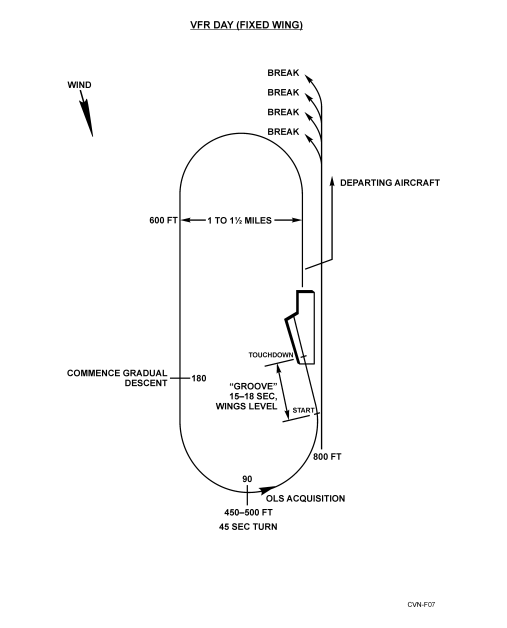 Figure 6-1. VFR Day Fixed Wing Carrier Landing Pattern
6.2.5 Voice Reports
Flight leaders shall make the following voice reports
| POSITION | REPORT |
| Descending from the port holding pattern | “Commencing” |
| Three miles astern | “Initial” |
| Entering spin pattern (when applicable) | “Spinning” |
| Departing the landing pattern to reenter port holding. | “Departing_______nm upwind” |
6.2.5.1 Low Visibility Voice Reports: Anyone Can Recommend Low Visibility Reports
The following additional calls shall be used by flight leaders upon Air Officer’s announcement of “99 low-vis-calls.”
“Commencing”
“Initial”
“Breaking at___nm”
“Departing at ___DME”
“Spin 90”
Flight leaders should amplify low-vis calls as required to add to overall situational awareness and safety of flight
(e.g. – “501, commencing from angels 4 with 2”).
6.2.6 ZIP LIP
Case I procedures shall apply, except for elimination of prescribed voice reports. The flight leader first in recovery
order shall observe the deck and plan his recovery to be at the ramp as soon as a ready deck is available. Should
unprogrammed, unbriefed, or straggler flights arrive for recovery, ZIP LIP shall be broken as required to ensure safety
of flight.
Note
ZIP LIP shall be broken anytime an apparent safety of flight situation
develops.
6.2.7 Drag
If a straight-in approach (drag) is requested, it shall be initiated at sufficient distance astern for the aircraft to be
established positively on glidepath and approach airspeed at a minimum of 1-1/2 nm for jet/turboprop aircraft.
6.3 CASE II
This approach shall be utilized when weather conditions are such that the flight may encounter instrument conditions
during the descent, but visual conditions of at least 1,000 feet ceiling and 5 miles visibility exist at the ship. Positive
control shall be utilized until the pilot is inside 10 nm and reports the ship in sight. During Case II recoveries, CATCC
shall be manned and prepared to assume control of a Case III recovery in the event weather conditions deteriorate.
The maximum number of aircraft in the landing pattern is limited to six.
Note
Case II recoveries shall not be conducted concurrently with Case III
departures. Should doubt exist regarding the ability to maintain VMC,
Case III recoveries shall be utilized.
Penetrations in actual instrument conditions by formation flights of more than two aircraft are not authorized. Flight
leaders shall follow Case III approach procedures outside of 10 nm. When within 10 nm with the ship in sight, flights
will be shifted to tower control and proceed as in Case I. If the flight does not have the ship in sight at 10 nm, the
flight may descend to not less than 800 feet. If a flight does not have the ship in sight at 5 miles, both aircraft shall
be vectored into the bolter/waveoff pattern and action taken to conduct a Case III recovery for the remaining flights.
Note
Weather conditions permitting, helicopters may be assigned Case I
procedures concurrently with Case II and III fixed-wing aircraft operations.
6.4 CASE III
This approach shall be utilized whenever existing weather at the ship is below Case II minimums and during all flight
operations conducted between one-half hour after sunset and one-half hour before sunrise except as modified by the
OTC or carrier commanding officer. Night/IMC Case III recoveries shall be made with single aircraft. Section
approaches will be approved only when an emergency situation exists. Formation penetrations/ approaches by
dissimilar aircraft shall not be attempted except in extreme circumstances where no safer options are available to
effect a recovery.
Note
Case III recoveries may be conducted concurrently with Case I and II
launches.
At night during VMC conditions, helicopters may be cleared to the starboard holding pattern. The same airspeed and
spacing restrictions will apply as in day VMC.
6.4.1 Marshal Procedures
6.4.1.1 Jet/Turboprop Aircraft
The primary TACAN marshal fix is the 180 radial relative to the expected final bearing at a distance of 1 mile for
every 1,000 feet of altitude plus 15 miles (angels +15). The holding pattern is a left-hand, 6-minute racetrack pattern.
The inbound leg shall pass over the holding fix. In no case will the base altitude be lower than 6,000 feet.
6.4.1.2 Helicopters
The primary TACAN marshal is the 110 radial relative to the expected final bearing at a distance of 1 mile for every
500 feet of altitude, starting at 1,000 feet and 5 miles. The holding pattern is a right-hand racetrack pattern with 2-nm
legs. The inbound leg shall pass over the holding fix.
6.4.1.3 Emergency Marshal Fixes
All fixed-wing aircraft are issued an emergency marshal radial 150 relative to the expected final bearing at a distance
of 1 mile for every 1,000 feet of altitude plus 15 miles (angels +15). Lowest altitude for assignment is 6,000 feet for
turboprop/jet. Holding sequence is jets, then turboprops. Holding procedures are right-hand, 6-minute racetrack
patterns. The inbound leg shall pass over the holding fix. Helicopter emergency marshal radial is the same as normal
helicopter marshal radial with helicopter emergency holding normally commencing at 7 miles.
6.4.1.4 Overhead Marshal
Overhead marshal may be utilized as geographical or operational circumstances necessitate. The assigned inbound
magnetic heading to the holding fix should coincide with the outbound magnetic radial of the approach. If overhead
marshal is used as the emergency marshal fix, EEATs should be every other minute.
6.4.1.5 En Route Radar Approaches
In the event an aircraft or flight cannot reach the marshal point in time to make an assigned approach time, an en route
radar approach may be used to place the flight in the proper approach sequence.
The marshal/approach controller shall employ positive radar control and provide the pilot the purpose and a brief
description of the intended penetration whenever possible.
6.4.1.6 Marshal Altitude Assignment
Every effort should be made to anticipate weather conditions and provide marshaling in visual conditions if practical.
Aircraft below an overcast should not be required to climb into the overcast to comply with base altitude limits if
marshal control can safely exercise control below the overcast. Those aircraft above an overcast should be assigned
altitudes above the overcast and retained in formation where possible. Formation flights shall be limited to a
maximum of four aircraft at any one assigned altitude. Under instrument conditions, a section of two aircraft is the
maximum number authorized in any one flight.
6.4.1.7 Marshal Altitude Separation
Fixed-wing aircraft will normally have a minimum of 1,000 feet verical separation.Vertical separation may be
reduced to 800 feet when inside 12 nm. Helicopters shall be separated by a minimum of 500 feet vertically.
6.4.1.8 Marshal Airspeed
Aircraft will normally fly at airspeeds in accordance with the applicable aircraft NATOPS flight manual.
6.4.1.9 Bow-On-Recovery
A bow-on-recovery occurs when the marshal radial is located ahead of the carrier. Significant potential conflict exists
between departing and recovering aircraft due to airspace constraints associated with opposite direction traffic flow
and the existence of an AN/SPN-43 radar “blind spot” ahead of the ship. CATCC shall communicate
bow-on-recovery to all aircrew as soon as bow-on-recovery is determined. Departing aircraft will receive positive
control to ensure departing aircraft remain clear of recovering aircraft until course conflict is resolved. CATCC shall
provide recovering aircraft positive control and sequencing to ensure adequate separation is maintained.
6.4.2 Marshal Instructions
Marshal control shall ensure the following information has been provided each aircraft prior to entering marshal:
- Case recovery
- Type approach
- Expected final bearing
- Altimeter
- Marshal holding instructions
- Expected approach time
- Expected approach button
- Time check
- Vector to marshal (if required)
- Multiple marshal stack information (radials/altitudes).
Note
When overhead marshal is utilized, the assigned outbound penetration
bearing shall be updated during recovery to maintain a minimum of 25
clockwise from the reciprocal of the final bearing.
6.4.3 General Instructions
The following information shall be provided prior to commencing the penetration/approach:
- Case recovery
- Type approach
- Final bearing
- Weather and deck conditions
- Divert field/fuel data
- Time hack (30 seconds minimum) using GPS time
- USW datum (if applicable)
- Density altitude (if applicable)
- MOVLAS recovery, including station number and location (tactical situation permitting)
- COD RETRO report (if applicable).
To reduce radio traffic, items of general or collective interest may be transmitted as a “99” broadcast by marshal or
approach control.
6.4.4 Departing Marshal
Each pilot shall adjust his holding pattern to depart marshal at the assigned EAT. Early or late departure shall be
reported to marshal control immediately so that control adjustments can be accomplished if required.
6.4.5 Initial Separation
Unless weather or operating circumstances dictate otherwise, aircraft departing marshal will normally be separated
by 1 minute. Adjustments may be directed by CATCC, if required, to ensure proper separation.
6.4.6 Frequency/IFF/SIF Changes
Changes in radio communication frequencies, IFF and/or SIF mode/code that require accomplishment by the pilot
should be made no later than platform except under emergency conditions. The aircraft shall be in straight and level
flight should such changes be required below an altitude of 2,500 feet.
6.4.7 Instrument Approach Procedures
The approaches described in this paragraph are designed primarily for single-carrier operations; however, with slight
modification, they can be used for the following:
- Multiple-carrier operations
- Letdown under reduced navigation and control
- Letdown using SAR as navigational aids with AEW control
- Recoveries during EMCON conditions.
The approach charts (Figures 6-2 to 6-5) are designed for use with all aircraft carriers regardless of weather conditions.
It is incumbent on each ship to utilize the standard approaches so that pilots may safely transition from ship to ship
or from visual to instrument conditions with a minimum change in operating procedures.
6.4.7.1 Approach Minimums
The commanding officer shall establish approach minimums that reflect significant changes in operational
capabilities, such as may be occasioned by decreased proficiency of the CATCC or embarked air wing. However,
absolute minimums are as provided in Figure 6-6 (see LSO NATOPS Manual for CARQUAL minimums).
When a suitable bingo field is available, aircraft shall not commence an approach if the reported weather is below
the minimums in Figure 6-6 unless it has been determined that the aircraft has sufficient fuel to proceed to the bingo
field in the event of a missed approach.
6.4.7.2 Penetration/Approach
- Jet/turboprop aircraft shall descend at 250 KIAS and 4,000 feet per minute until platform is reached, at which
point the descent shall be shallowed to 2,000 feet per minute. Unless otherwise directed, aircraft shall
commence transition to a landing configuration at the 8-nm fix. - Helicopters shall descend at 90 knots and 500 feet per minute from marshal, crossing 145 relative to the final
bearing at or above 900 feet. Unless otherwise directed, helicopters shall commence transition to a landing
configuration prior to the 3-nm fix.
6.4.7.3 Correcting to the Final Bearing
- Jet or turboprop aircraft on the CV-1 approach will correct from the marshal radial to the final bearing at 20
miles in the following manner:- The pilot shall make a gradual correction when the final bearing is within 10 of the reciprocal of the
marshal radial. - The pilot shall turn 30 when the final bearing is greater than 10 from the reciprocal of the marshal radial.
If not established on the final bearing at 12 miles, the pilot shall fly the 12-mile arc until intercepting final
bearing.
- The pilot shall make a gradual correction when the final bearing is within 10 of the reciprocal of the
- Aircraft on the CV-2 approach shall correct to the final bearing in the following manner:
- If final bearing decreases, fly 90 of penetration turn and arc to the new final bearing.
- If final bearing increases, fly the standard penetration turn continuing to intercept the new final bearing prior
to the 10-mile DME fix.
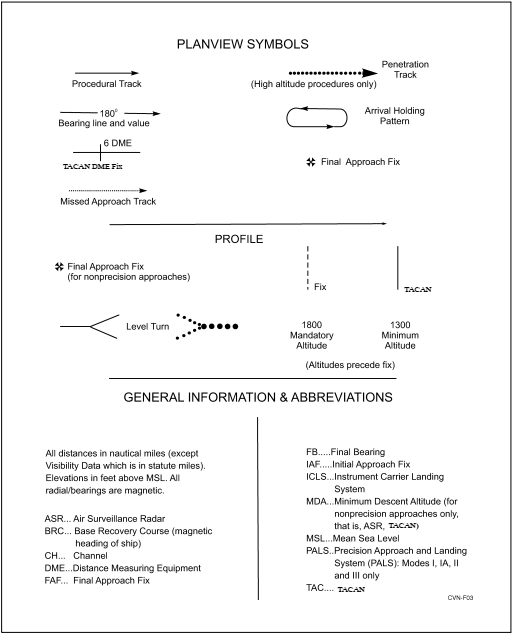 Figure 6-2. Legend Chart for Aircraft Carrier Instrument Approach Proceduress
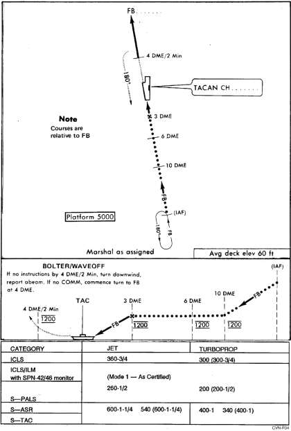
Figure 6-3. Approach Chart CV-1 TACAN (Jet and Turboprop)
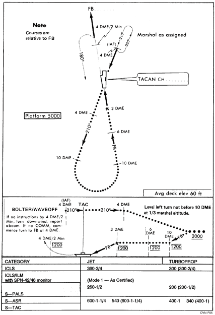
Figure 6-4. Approach Chart CV-2 TACAN Overhead (Jet and Turboprop)
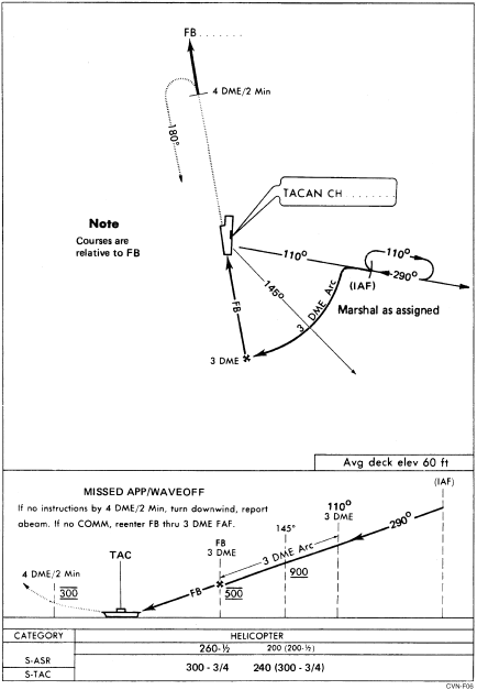
Figure 6-5. Approach Chart CV-3 TACAN (Helicopter)
6.4.8 Missed Approach/Waveoff/Bolter
Jet and turboprop aircraft shall climb straight ahead on the extended final bearing to 1,200 feet altitude and wait for
instructions from approach control.
Helicopters shall climb straight ahead on the extended final bearing to 300 feet altitude and await instructions from
approach control.
All waveoff/bolter pattern turns shall be level.
If no instructions are received prior to reaching 4 miles or 2 minutes ahead of the ship, the pilot will attempt to make
contact with the ship, giving identification and position. If instructions are not received, he will assume
communication failure and execute a turn downwind reporting downwind abeam. If radio contact is not reestablished,
he will proceed downwind and reenter as follows:
- Fixed-wing aircraft commence turn to final at the 4 nm DME or 2 minutes past abeam position.
- Helicopters reenter through the 3 nm DME fix or turn inbound 2 minutes past abeam.
- PALS aircraft shall be alert for data-link displays.
6.7 SPECIAL PROCEDURES FOR CARRIER QUALIFICATION LANDING
6.7.1 Fixed-Wing Aircraft
The number of aircraft in the Case I or II pattern should be limited to four and shall not exceed six.
Maintaining a proper and uniform interval is very important in the CARQUAL pattern. The air operations officer
and the air officer shall make appropriate recommendations. Jet/turboprop aircraft night CARQUALs shall be under
CCA control. Advisory control may be specified by the ship’s commanding officer when weather permits.
The air officer must be acutely aware of the responsibility to ensure the
initial separation between bolter/waveoff and departing aircraft during
CARQUAL and cat-trap-cat evolutions.
NAVAIR 00-80T-105
ORIGINAL 6-30
CATCC’s restricted radar coverage (blindspot) ahead of the ship requires
aircrew to exercise good lookout doctrine and radio discipline upon
departure.
During night CARQUALs, CCA shall utilize a single frequency to control all aircraft in the CARQUAL pattern.
Anytime CARQUAL or refresher landings are being conducted, a senior representative of each squadron involved
should be present in the tower. During IMC and night operations, his station will be in air operations. He must be
well qualified in the aircraft and prepared to advise the air officer in the event of an emergency.
It is the responsibility of the air operations officer to keep the air officer accurately apprised of the number of landings
required for each aircraft. Air operations/ CATCC will maintain a status board that will show landings required,
landings completed, and location of each aircraft (in Delta, in the Charlie pattern, or on the deck).
The air operations officer is responsible for providing the air officer with accurate bingo/divert data. Before
commencing and/or during CARQUALs, he shall compute the distance and bearing to the bingo/divert field and the
fuel required for the model aircraft involved. Bingo/divert data will be broadcast on the recovery frequency by PriFly
or CCA as appropriate.
The decision to divert aircraft will be made by the commanding officer or his designated representative. The air
operations officer and the air officer shall make appropriate recommendations during IMC/night and VMC
operations, respectively. In addition, the LSO will make timely divert recommendations to the air officer based on
unsatisfactory pilot performance or unsatisfactory CARQUAL conditions around the ship. It is the pilot’s
responsibility to inform the tower if he reaches bingo fuel state and has not been ordered to divert.
Changing pilots when an aircraft is on the flight deck with engine(s) running is an inherently dangerous practice
requiring extreme care. When a change is made, the aircraft shall be chocked and have at least the initial tiedowns
attached. Pilots shall not leave/switch their seats until given the “tiedowns in place” signal by the aircraft director.
Note
It is the pilot’s responsibility to inform the tower when reaching holddown
fuel state after trapping and the aircraft has not been taxied to a refueling
spot.
6.7.2 Helicopters
When feasible, two landing spots will be utilized for CARQUAL landings. The pattern shall be a left-hand racetrack
on the port side of the ship. Pattern spacing shall be adjusted to permit one aircraft to be launched prior to another
being landed. When the pilot acquires the meatball, he shall report his side number, “ball,” and “gear down.”
Night CARQUALs shall be under CCA control. Advisory control may be specified by the ship’s commanding officer
when weather permits.
The pilot in the right seat shall be in control of the aircraft unless the tower is informed to the contrary. When changing
pilots, the aircraft will be chocked and have initial tiedowns attached.
NAVAIR 00-80T-105
ORIGINAL6-31
6.8 EMERGENCY LANDING
6.8.1 Fixed-Wing Aircraft
At first indication of a possible emergency landing, the air officer will pass the word “stand by to make a ready deck.”
At this time, arresting gear and Crash Salvage personnel, ILARTS, and lens operators will immediately man their
stations. It is the responsibility of PriFly to contact the LSO, who will proceed to the platform. The squadron duty
officer will be notified. Tractors will be attached to all aircraft parked in the landing area, tiedowns will be removed
when directed by the plane directors, and directors and chock men will stand by. A helicopter should be manned and
started unless an airborne helicopter is available for plane guard. If the emergency condition requires a straight-in
approach or a straight-in approach is contemplated, the SPN-41 shall immediately be activated without pilot request.
When it has been determined that an emergency landing will be made, the Air Officer will pass the word, “Make a
ready deck,” at which time the landing area will be cleared as expeditiously as safety permits. Personnel concerned
will stand by to rig the barricade if called for. The air officer shall pass an expected Charlie time to the distressed
aircraft.
Pilots of aircraft returning to the ship for an emergency landing shall not shift from the control frequency to tower
frequency until directed to do so unless radio contact has been lost on the control frequency. Normally, the tower and
LSO will shift to the control frequency, thereby avoiding the necessity of a frequency change by the pilot. In no case
will the pilot of an aircraft in distress leave an assigned frequency without broadcasting the frequency to which he
is shifting.
As the ship is being prepared for the landing of aircraft, the air officer will pass as much pertinent information as
possible to the flight deck, bridge, LSO, and CATCC. The air officer shall determine the amount and type of
firefighting equipment to be broken out and direct the deployment of personnel, depending upon the nature and
seriousness of the emergency.
6.8.2 Helicopters
As much deck space as possible will be made available for emergency helicopter landings. If time permits, the senior
helicopter squadron or unit officer on board should take station in the tower or in CATCC, and the air officer should
determine the optimum relative wind and request the bridge to maneuver the ship as necessary. In clearing a helicopter
for an emergency landing, PriFly will ordinarily designate an area of the flight deck rather than a specific landing
spot. Once the aircraft is on final approach, it is imperative that the ship hold a steady course.
During an emergency landing, the LSE, if immediately available, shall stand at the upwind edge of the designated landing
area. The LSE signals are advisory in nature, except for the waveoff and hold signals, which are mandatory. The LSE
shall give a waveoff only in case of a foul deck or if instructed by the tower to do so.
6.9 EMERGENCY SIGNALS
6.9.1 Visual Signals to Ship From Aircraft With Radio Failure
Figures 6-7 and 6-8 provide visual signals to be used in the event of radio failure. Aircraft configuration is the primary
daytime indicator of the pilot’s desires or intentions. At night, aircraft lighting configuration is the primary indicator
of the pilot’s desires or intentions.
6.9.2 Visual Signals to Aircraft From Ship Under EMCON or Lost Communication Conditions
Figure 6-9 provides visual signals for giving commands or advisories to aircraft when the ship has lost its
communication capability or is under EMCON conditions.
NAVAIR 00-80T-105
ORIGINAL 6-32
6.9.3 Carrier Pattern Emergencies
The LSO will make appropriate recommendations to the air officer or pilot as indicated in Figure 6-10.
6.9.4 Day Communication Emergencies
Figure 6-11 describes appropriate action for day communication emergencies.
6.9.5 Night Communication Emergencies
Figure 6-12 describes appropriate action for night communication emergencies.
6.10 TANKER OPERATIONS
Tankers assigned duties in support of the recovery of aircraft shall use the following procedures:
1. Only those tankers that have a known good store and sufficient fuel to meet receiver fuel requirements shall
display the flashing green light.
2. For optimum utilization of tankers, single-cycle operation is recommended.
3. A specific existing agency (i.e., departure control) shall be designated tanker control with the responsibility
to monitor:
a. Tanker give-away fuel status
b. Tanker location
c. Location and fuel requirements of the low state aircraft
d. Coordination of the tanker and receiver rendezvous.
6.10.1 Recovery Tanker Procedures
6.10.1.1 CASE I/II
After launch, the oncoming recovery tanker shall switch to departure control for assignment. All tanker packages
should be checked as soon as possible after launch. When it has been determined that the new tanker store is
operational, departure control should be advised immediately. The recovery tanker shall maintain a rendezvous circle
oriented on the CV (Figure 6-13). The rendezvous circle shall contain four reference points. Minimum pattern altitude
shall be 1,500 feet. This pattern is a left-hand circle within 5 nm of the CV during launch and recovery operations.
When the last jet is aboard, the tanker shall climb to prebriefed altitude and switch to assigned frequency for
control.
| PILOT’S DESIRES OR INTENTIONS | VISUAL SIGNAL |
|
I desire immediate landing. |
Fly up the port side of the ship, low and close aboard, rocking wings, in a landing configuration with hook down. Navigation lights bright and steady with anticollision light on. If turning final in VFR pattern or approaching final on a CCA, momentarily turn on the taxi light, if available. |
|
I desire to land but can wait for the next recovery. |
Fly up the port side with the landing gear up, hook down, navigation lights bright and steady, and anticolli- sion light off while abeam the ship. |
|
I am proceeding to the bingo field. |
Fly up the port side of the ship, rocking wings, with landing gear and hook up, navigation lights bright and steady, and anticollision light on. If fuel state and nature of the emergency permit, continue making passes until joined by a wingman. Upon reaching bingo fuel state, proceed alone, setting IFF/SIF to emergency when departing. |
|
NOTE
|
|
Figure 6-7. Emergency Signals to Ship From Fixed-Wing Aircraft With Radio Failure
| PILOT’S DESIRES OR INTENTIONS | VISUAL SIGNAL |
| I require immediate landing. | Fly close aboard starboard quarter, remaining clear of other traffic, with gear down and floodlights/landing light on. With complete electrical failure, fire a red flare to seaward. |
| I desire to land but can wait for the next recovery. | Fly by or hover on the starboard side of the ship, low and close aboard, with navigation lights bright and flashing and anticollision light on. |
Figure 6-8. Emergency Signals to Ship From Helicopters With Radio Failure
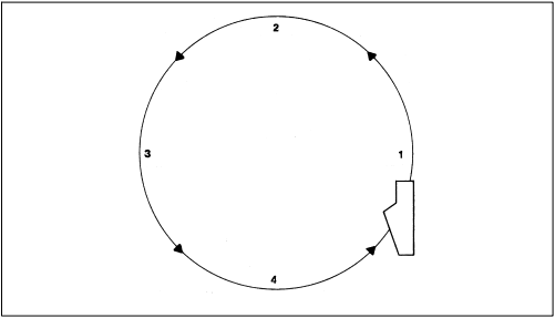
Figure 6-13. Tanker Rendezvous Pattern
6.10.1.2 Case III
The recovery tanker pattern shall be assigned by departure control. It shall be at least 1,000 feet above the overcast
or VMC between layers, but not less than 2,500 feet MSL. The tanker pilot shall advise departure control of the best
altitude and position to conduct emergency tanking. Positive control shall be provided for tanker overcast
penetrations. Departure control shall assist in positioning the tanker near a potential receiver and shall keep the tanker
informed of the potential receiver’s position.
Note
Tanking shall not be attempted below 1,500 feet during Case I/II and 2,500
feet during Case III.
6.10.2 Rendezvous Procedures
6.10.2.1 Rendezvous Low (Day and Night)
When directed to “hawk” (closely monitor) a particular aircraft that is a potential receiver, the tanker pilot shall
position the tanker to be at the 2-o’clock position of the low-state aircraft as it bolters or waves off. The minimum
altitude for rendezvous shall be 1,500 feet day, 2,500 feet night, ensuring a minimum of 500 feet vertical separation
between receiver and tanker aircraft until visual separation can be maintained. When directed, the tanker shall switch
to the potential receiver aircraft’s frequency. If visual contact is not acquired, the controlling agency shall provide
assistance until visual contact is established. The receiver should generally make the final rendezvous on the tanker.
Positive radio communications must be established if the tanker will be rendezvousing on the receiver at night. The
tanker should stream the drogue as the receiver joins, thus expediting plug-in. The tanker pilot shall report to tanker
control the following:
1. When the receiver is taking on fuel
2. When refueling has been completed, the amount of fuel transferred, and update give-away.
6.10.2.2 Rendezvous High/On Top (Day and Night)
Departure control shall provide positive control until visual contact is established. The receiver shall make the final
rendezvous on the tanker and report as previously described.
6.10.3 Recovery Tanking Pattern
After the receiver is engaged, the tanker aircraft shall establish a racetrack pattern in the vicinity of the ship. Unless special
circumstances exist, the tanker should not proceed more than 10 miles ahead of the ship. The downwind leg should be
3 to 5 miles abeam and tanking should be completed prior to reaching a point 6 miles astern to allow for proper pattern
entry. If tanking is done above an overcast, departure control may direct adjustment of the pattern so as to allow for normal
descent and CCA pickup.
6.10.4 Recovery (Case III)
The desire to expedite tanker recovery must not jeopardize flight safety. The recovery tanker shall be given positive
control unless executing an instrument approach procedure published in this section or operating under night
EMCON conditions. The aircraft shall be level during the turn to final bearing and given sufficient clearance to pass
through 6 miles at 1,200 feet.
Note
If recovery tanker is established 1,200 feet abeam, the six mile gate is not
required.
NAVAIR 00-80T-105
ORIGINAL 6-40
6.10.5 Fuel Transfer and Dump Control
Each ship/air wing shall promulgate supplementary instructions that shall include the following instructions.
1. Bingo data for all embarked aircraft.
2. Low state figures (i.e., state at which aircraft will normally be ordered to tank) and amount of fuel to be
transferred to each type aircraft when no divert field is available.
3. Procedures for control of tanker fuel by CATCC.
4. Minimum fuel for barricade engagement.
Except in an emergency, tankers shall obtain clearance from departure control before transferring or dumping fuel.
Departure control shall be advised of any changes of tanker fuel state and give-away as appropriate.
Shipboard recovery of a tanker aircraft with an extended hose presents a
missile hazard that may be caused by shattering of the drogue/basket as it
strikes the ramp area. Prior to recovery, the flight deck should be cleared
of all but required recovery personnel. Only the controlling LSO should
remain on the platform, and he should utilize the safety net as the aircraft
crosses the ramp. If possible, aircraft adjacent to the landing area should be
respotted forward or struck below to the hangar deck.
Even though the probability of damage to the aircraft by drogue/basket slap
during a bolter is slight, the pilot should be aware of this possibility.
6.11 DIVERSION OF AIRCRAFT
The air operations officer or the air officer shall normally be responsible for making the recommendation to the
commanding officer as to which aircraft should be diverted in the interest of flight safety. The air operations officer
shall, if practicable, determine the condition of the navigation, communication, and lighting facilities of divert field
prior to the first Case III recovery. The following factors shall be considered when anticipating a divert:
1. Aircraft fuel state
2. Bearing and distance of field
3. Weather at divert field, current and forecast
4. En route upper level winds
5. Suitability of field for type of aircraft
6. Navigational assistance available
7. Aircraft mechanical condition
8. Ordnance restrictions
NAVAIR 00-80T-105
ORIGINAL6-41/(6-42 blank)
9. Condition of carrier deck
10. Availability of tankers
11. Pilot performance.
CATCC/CDC shall be alerted to the impending divert of an aircraft or group of aircraft and shall take control of the
aircraft when diverted. CDC shall also ensure the ship’s lookouts are alerted to the forthcoming divert, model aircraft,
side number, and on what relative bearing the aircraft is expected to depart the ship.
If the tanker refueling hose cannot be retracted, the hose shall be guillotined prior to recovery. If the hose fails to
separate, the aircraft shall be diverted to a suitable landing field. When the situation prevents an aircraft divert and
it is equipped with an external refueling store, the store shall be jettisoned prior to attempting a carrier landing. If
the hose cannot be guillotined and/or the refueling store jettisoned, normal arrested landing procedures shall be
utilized.
When it is determined to divert an aircraft, approach control shall notify the pilot by passing the following information
only: “(call sign) signal divert/bingo, (name of field) passing angles 2.5 go button (XX).” After the switch to departure
control once above 2,500 feet, the pilot shall be advised to check gear up/hook up and also have information relayed
regarding the magnetic heading and the distance to the divert field. A readback of diverting instructions from the pilot
or flight leader is mandatory on departure frequency. While under positive control and en route to the divert airfield,
any additional information available shall be provided the pilot concerning latest en route and field weather, squawk,
altimeter setting, and position from which divert is being initiated. If operating outside an ADIZ boundary, the CDC
controller shall provide the pilot with the necessary ADIZ information. The appropriate Air Defense Sector shall be
advised of the diverted aircraft’s departure point, ADIZ penetration point, time of penetration, altitude, ETE,
destination, and any additional information that may be pertinent to safety of flight. The CDC controller shall
maintain a radar plot and radio monitor on all diverted aircraft as long as possible and retain responsibility for the
aircraft until positive radar handoff to FACSFAC/ARTCC or other appropriate controlling agency.
Under IMC, the aircraft shall be instructed to shift to the appropriate airspace controlling agency (FAA or other)
frequency after the additional divert information has been received. Once communications have been established
with this controlling agency, the flight plan particulars shall be furnished, including the ADIZ penetration
information for relay to an air defense sector. The aircraft will receive a clearance. If communications cannot be
established, as is often the case, the pilot should file using GCI Common.
The air operations officer shall ensure a divert flight plan is transmitted to the appropriate divert airfield and similar
information to the pertinent air defense system agency should an ADIZ penetration be involved; he is also responsible
for receipt of an arrival report on the diverted aircraft. The pilot shall ensure an arrival report is transmitted
immediately upon landing via the most expeditious means (i.e., POTS, HF/UHF radio, INMARSAT, immediate
message, etc.).
Squadron or unit commanders and the air operations officer are jointly responsible for ensure aircraft performance
data pertinent to divert is available to and understood by air control personnel.
Flight Documents
- Briefings
- Kneeboards
- Flight Charts
- Situation Briefs
Kneeboard Examples 11.07.25